


Published on Feb 14, 2025
Non-Destructive Testing (NDT) is a wide group of analysis techniques used in science and industry to evaluate the properties of a material, component or system without causing damage. The terms Nondestructive examination (NDE), Nondestructive inspection (NDI), and Nondestructive evaluation (NDE) are also commonly used to describe this technology.
Because NDT does not permanently alter the article being inspected, it is a highly-valuable technique that can save both money and time in product evaluation, troubleshooting, and research.
Non-destructive Testing is one part of the function of Quality Control and is Complementary to other long established methods. By definition non-destructive testing is the testing of materials, for surface or internal flaws or metallurgical condition, without interfering in any way with the integrity of the material or its suitability for service.
The technique can be applied on a sampling basis for individual investigation or may be used for 100% checking of material in a production quality control system. Whilst being a high technology concept, evolution of the equipment has made it robust enough for application in any industrial environment at any stage of manufacture - from steel making to site inspection of components already in service.
A certain degree of skill is required to apply the techniques properly in order to obtain the maximum amount of information concerning the product, with consequent feed back to the production facility. Non-destructive Testing is not just a method for rejecting substandard material; it is also an assurance that the supposedly good is good. The technique uses a variety of principles; there is no single method around which a black box may be built to satisfy all requirements in all circumstances.
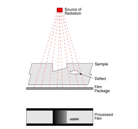
This technique is suitable for the detection of internal defects in ferrous and nonferrous metals and other materials. X-rays, generated electrically, and Gamma rays emitted from radio-active isotopes, are penetrating radiation which is differentially absorbed by the material through which it passes; the greater the thickness, the greater the absorption. Furthermore, the denser the material the greater the absorption.
X and Gamma rays also have the property, like light, of partially converting silver halide crystals in a photographic film to metallic silver, in proportion to the intensity of the radiation reaching the film, and therefore forming a latent image. This can be developed and fixed in a similar way to normal photographic film. Material with internal voids is tested by placing the subject between the source of radiation and the film. The voids show as darkened areas, where more radiation has reached the film, on a clear background. The principles are the same for both X and Gamma radiography.
In X-radiography the penetrating power is determined by the number of volts applied to the X-Ray tube - in steel approximately 1000 volts per inch thickness is necessary. In Gamma radiography the isotope governs the penetrating power and is unalterable in each isotope. Thus Iridium 192 is used for 1/2" to 1" steel and Caesium 134 is used for 3/4" to 21/2" steel. In X-radiography the intensity, and therefore the exposure time, is governed by the amperage of the cathode in the tube. Exposure time is usually expressed in terms of milliampere minutes. With Gamma rays the intensity of the radiation is set at the time of supply of the isotope. The intensity of radiation from isotopes is measured in Becquerel’s and reduces over a period of time.
The time taken to decay to half the amount of curies is the half life and is characteristic of each isotope. For example, the half life of Iridium 192 is 74 days, and Caesium 134 is 2.1 years. The exposure factor is a product of the number of curies and time, usually expressed in curie hours. The time of exposure must be increased as the isotope decays - when the exposure period becomes uneconomical the isotope must be renewed. As the isotope is continuously emitting radiation it must be housed in a container of depleted uranium or similar dense shielding material, whilst not exposed to protect the environment and personnel.
This method is suitable for the detection of surface and near surface discontinuities in magnetic material, mainly ferrite steel and iron. An Illustration of the Principle of Magnetic Particle Inspection
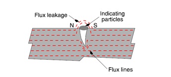
The principle is to generate magnetic flux in the article to be examined, with the flux lines running along the surface at right angles to the suspected defect. Where the flux lines approach a discontinuity they will stay out in to the air at the mouth of the crack. The crack edge becomes magnetic attractive poles North and South. These have the power to attract finely divided particles of magnetic material such as iron fillings. Usually these particles are of an oxide of iron in the size range 20 to 30 microns, and are suspended in a liquid which provides mobility for the particles on the surface of the test piece, assisting their migration to the crack edges. However, in some instances they can be applied in a dry powder form.
The particles can be red or black oxide, or they can be coated with a substance, which fluoresces brilliantly under ultra-violet illumination (black light). The object is to present as great a contrast as possible between the crack indication and the material background. The technique not only detects those defects which are not normally visible to the unaided eye, but also renders easily visible those defects which would otherwise require close scrutiny of the surface. There are many methods of generating magnetic flux in the test piece, the simplest one being the application of a permanent magnet to the surface, but this method cannot be controlled accurately because of indifferent surface contact and deterioration in magnetic strength. Modern equipments generate the magnetic field electrically either directly or indirectly. Eddy Current and Electro-Magnetic Methods
The main applications of the eddy current technique are for the detection of surface or subsurface flaws, conductivity measurement and coating thickness measurement. The technique is sensitive to the material conductivity, permeability and dimensions of a product. Eddy currents can be produced in any electrically conducting material that is subjected to an alternating magnetic field (typically 10Hz to 10MHz). The alternating magnetic field is normally generated by passing an alternating current through a coil. The coil can have many shapes and can between 10 and 500 turns of wire.
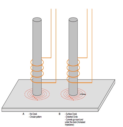
The magnitude of the eddy currents generated in the product is dependent on conductivity, permeability and the set up geometry. Any change in the material or geometry can be detected by the excitation coil as a change in the coil impedance The most simple coil comprises a ferrite rod with several turns of wire wound at one end and which is positioned close to the surface of the product to be tested. When a crack, for example, occurs in the product surface the eddy currents must travel farther around the crack and this is detected by the impedance change
www.ndt-ed.org
www.google.com
www.wikipedia.com
www.InsightNDT.com.
| Are you interested in this topic.Then mail to us immediately to get the full report.
email :- contactv2@gmail.com |
