


Published on Feb 14, 2025
To eliminate the cam, camshaft and other connected mechanisms, the Camless engine makes use of three vital components - the sensors, the electronic control unit and the actuator.
Mainly five sensors are used in connection with the valve operation. One for sensing the speed of the engine, one for sensing the load on the engine, exhaust gas sensor, valve position sensor and current sensor. The sensors will send signals to the electronic control unit. The electronic control unit consists of a microprocessor, which is provided with a software algorithm. The microprocessor issues signals to the solid-state circuitry based on this algorithm, which in turn controls the actuator, to function according to the requirements.
In the past, electro hydraulic camless systems were created primarily as research tools permitting quick simulation of a wide variety of cam profiles. For example, systems with precise modulation of a hydraulic actuator position in order to obtain a desired engine valve lift versus time characteristic, thus simulating the output of different camshafts. In such systems the issue of energy consumption is often unimportant. The system described here has been conceived for use in production engines. It was, therefore, very important to minimize the hydraulic energy consumption.
The Electro hydraulic Camless Valve train, (ECV) provides continuously variable control of engine valve timing, lift, and velocity. It uses neither cams nor springs. It exploits the elastic properties of a compressed hydraulic fluid, which, acting as a liquid spring, accelerates and decelerates each engine valve during its opening and closing motions. This is the principle of the hydraulic pendulum. Like a mechanical pendulum," the hydraulic pendulum involves conversion of potential energy into kinetic energy and, then, back into potential energy with minimal energy loss". During acceleration, potential energy of the fluid is converted into kinetic energy of the valve.
During deceleration, the energy of the valve motion is returned to the fluid. This takes place both during valve opening and closing. Recuperation of kinetic energy is the key to the low energy consumption of this system.. Figure 7 illustrates the hydraulic pendulum concept. The system incorporates high and low-pressure reservoirs. A small double-acting piston is fixed to the top of the engine valve that rides in a sleeve. The volume above the piston can be connected either to a high- or a low-pressure source.
The volume below the piston is constantly connected to the high-pressure source. The pressure area above the piston is significantly larger than the pressure area below the piston. The engine valve opening is controlled by a high-pressure solenoid valve that is open during the engine valve acceleration and closed during deceleration. Opening and closing of a low-pressure solenoid valve controls the valve closing. The system also includes high and low-pressure check valves.
During the valve opening, the high-pressure solenoid valve is open, and the net pressure force pushing on the double-acting piston accelerates the engine valve downward. When the solenoid valve closes, pressure above the piston drops, and the piston decelerates pushing the fluid from the lower volume back into the high-pressure reservoir. Low-pressure fluid flowing through the low-pressure check valve fills the volume above the piston during deceleration. When the downward motion of the valve stops, the check valve closes, and the engine valve remains locked in open position. The process of the valve closing is similar, in principle, to that of the valve opening.
The low-pressure solenoid valve opens, the pressure above the piston drops to the level in the low pressure reservoir, and the net pressure force acting on the piston accelerates the engine valve upward. Then the solenoid valve closes, pressure above the piston rises, and the piston decelerates pushing the fluid from the volume above it through the high-pressure check valve back into the high-pressure reservoir.
The hydraulic pendulum is a spring less system. Figure 8 shows idealized graphs of acceleration, velocity and valve lift versus time for the hydraulic pendulum system. Thanks to the absence of springs, the valve moves with constant acceleration and deceleration. This permits to perform the required valve motion with much smaller net driving force, than in systems which use springs. The advantage is further amplified by the fact that in the spring less system the engine valve is the only moving mechanical mass. To minimize the constant driving force in the hydraulic pendulum the opening and closing accelerations and decelerations must be equal
An alternative to the conventional poppet valve for use in camless valve trains is a ball valve. This type of electromechanical valve system consists of a ball through which a passage passes. If the ball is rotated such that the passage lines up with other openings in the valve assembly, gas can pass through it. (Exactly like the ball valves many of us use valve is accomplished by electromagnets positioned around its exterior to control our boost).
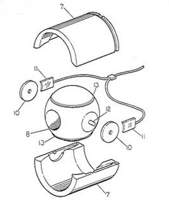
Figure 6:Assembly Of Electromechanical Ball Valve
Referring to Figure 6, the valve housing (7) is shown in two pieces. Ball valve (8) has two rigidly attached pivots (12). The disc (10) is permanently attached and indexed to the ball valve and contains permanent magnets around its perimeter. The electromagnets (11) are situated on both sides of the ball valve (8) and they are fixed to the valve housing. The electromagnets are controlled through the ECU. A crank trigger sensor on the crankshaft provides information about the position of the pistons relative to top dead centre. Thus, at top dead centre of the power stroke, the ECM could be used to fix the polarity of both electromagnets so that they are of opposite polarity to the magnets in the ball valve, rotating the ball valve to the closed position.
The substitution of a simple, efficient ball valve and valve housing arrangement in a four stroke reciprocation piston engine eliminates all the independent moving parts in the valve train. This may even be an improvement over the poppet valve camless system - the ball valve needs only to rotate on its axis to achieve the desired flow conditions, rather than be accelerated up and down in a linear fashion. A partially open ball valve state may also be able to be used to create more turbulence.
Electromechanical valve train implementation would not be possible with a normal 12V electrical system. The automotive industry has chosen a 42V electrical system as the next automotive standard. Consequently, the energy demand of EMVT can be optimally matched by a crankshaft-mounted starter-generator (KSG - in Siemens speak) operating at 42V; it is integrated in the flywheel and designed for the starting process as well as generator operation
Electro hydraulic camless valve train offers a continuously variable and independent control of all aspects of valve motion. This is a significant advancement over the conventional mechanical valve train. It brings about a system that allows independent scheduling of valve lift, valve open duration, and placement of the event in the engine cycle, thus creating an engine with a totally uncompromised operation.
Additionally, the ECV system is capable of controlling the valve velocity, perform selective valve deactivation, and vary the activation frequency. It also offers advantages in packaging. Freedom to optimize all parameters of valve motion for each engine operating condition without compromise is expected to result in better fuel economy, higher torque and power, improved idle stability, lower exhaust emissions and a number of other benefits and possibilities.
Camless engines have a number of advantages over conventional engines.
• In a conventional engine, the camshaft controls intake and exhaust valves. Valve timing, valve lift, and event duration are all fixed values specific to the camshaft design. The cams always open and close the valves at the same precise moment in each cylinder’s constantly repeated cycle of fuel-air intake, compression, combustion, and exhaust. They do so regardless of whether the engine is idling or spinning at maximum rpm. As a result, engine designers can achieve optimum performance at only one speed. Thus, the camshaft limits engine performance in that timing, lift, and duration cannot be varied.
• The improvement in the speed of operation valve actuation and control system can be readily appreciated with reference to Figure 9. It shows a comparison between valve speeds of a mechanical camshaft engine and the camless engine valve actuation
| Are you interested in this topic.Then mail to us immediately to get the full report.
email :- contactv2@gmail.com |
