


Published on Jan 09, 2026
Blended Wing Body (BWB) aircraft have a flattened and airfoil shaped body, which produces most of the lift, the wings contributing the balance. The body form is composed of distinct and separate wing structures, though the wings are smoothly blended into the body. For more visit- www.akfunworld.co.nr Page 2 Blended Wing Body By way of contrast, flying wing designs are defined as a tailless fixed-wing aircraft which has no definite fuselage, with most of the crew, payload and equipment being housed inside the main wing structure.
Blended wing body has lift-to-drag ratio 50% greater than conventional airplane. Thus BWB incorporates design features from both a futuristic fuselage and flying wing design. The purported advantages of the BWB approach are efficient high-lift wings and a wide airfoil- shaped body. This enables the entire craft to contribute to lift generation with the result of potentially increased fuel economy and range.
A flying wing is a type of tail-less aircraft design and has been known since the early days of aviation. Since a wing is necessary of any aircraft, removing everything else, like the tail and fuselages, results in a design with the lowest possible drag. Successful applications of this configuration are for example the H-09 and later H-0229 developed by Horton Brothers for Nazi’s during 1942.
Latter Northrop started designing flying such as NIM in 1942 and later XB- 35 Bomber which flew first in 1942. In 1988, when NASA Langley Research Centre’s Dennis Bushnell asked the question: “Is there a renaissance for the long haul transport?” there was cause for reaction. In response, a brief preliminary design study was conducted at McDonnell Douglas to create and evaluate alternate configurations. A preliminary configuration concept, shown in Fig. 1.4, was the result.
Here, the pressurized passenger compartment consisted of adjacent parallel tubes, a lateral extension of the double-bubble concept. Comparison with a conventional configuration airplane sized for the same design mission indicated that the blended configuration was significantly lighter, had a higher lift to drag ratio, and had a substantially lower fuel burn. In modern era after B-2 Bomber (1989) blended wing body was used for stealth operations.
The unmanned combat air vehicle (UCAV) named X-47 in year 2003 was subjected to test flights. Flight test began on 20th July and the first flight reached an altitude of 7500 feet MSL (2286 m) and lasted for 31 min. On 4th September first remotely piloted aircraft was stalled. Latest being the NASA and Boeing successfully completed initial flight testing of Boeing X-48B on March 19, 2010. The Blended Wing Body (BWB) is the relatively new aircraft concept that has potential use as a commercial or military use aircraft, cargo delivery or as fuel tanker
NASA Langley Research Centre funded a small study at McDonnell Douglas to develop and compare advanced technology subsonic Transports for the design mission of 800 passengers and a 7000-n mile range at a Mach number of 0.85.Composite structure and advanced technology turbofans were utilized. Defining the pressurized passenger cabin for a very large airplane offers two challenges.
First, the square-cube law* shows that the cabin surface area per passenger available for emergency egress decreases with increasing passenger count. Second, cabin pressure loads are most efficiently taken in hoop tension. Thus, the early study began with an attempt to use circular cylinders for the fuselage pressure vessel, along with the corresponding first cut at the airplane geometry. The engines are buried in the wing root, and it was intended that passengers could egress from the sides of both the upper and lower levels. Clearly, the concept was headed back to a conventional tube and wing configuration.
Therefore, it was decided to abandon the requirement for taking pressure loads in hoop tension and to assume that an alternate efficient structural concept could be developed. Removal of this constraint became pivotal for the development of the BWB. Passenger cabin definition became the origin of the design, with the hoop tension structural requirement deleted. Three canonical forms shown in Fig 2.1a, each sized to hold 800 passengers were considered. The sphere has minimum surface area; however, it is not stream lined.
Two canonical stream lined options include the conventional cylinder and a disk, both of which have nearly equivalent surface area. Next, each of these fuselages is placed on a wing that has a total surface area of 1393.54 sq-m. Now the effective masking of the wing by the disk fuselage results in a reduction of total aerodynamic wetted area of 650 sq-m compared to the cylindrical fuselage plus wing geometry, as shown in Fig 2.1b.
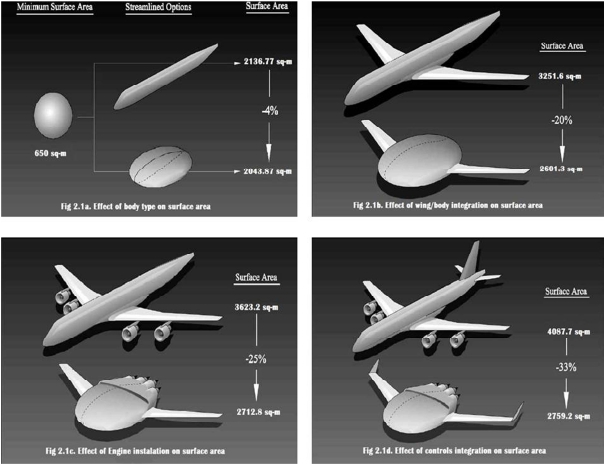
Next, adding engines (Fig 2.1c) provides a difference in total wetted area of 947.6 sq-m. (Weight and balance require that the engines be located aft on the disk configuration.) Finally, adding the required control surfaces to each configuration as shown in Fig 2.1d results in a total wetted area difference of 1328.5 sq-m, or a reduction of 33%. Because the cruise lift to drag For more visit- www.akfunworld.co.nr Page 6 Blended Wing Body ratio is related to the wetted area aspect ratio, the BWB configuration implied a substantial improvement in aerodynamic efficiency.
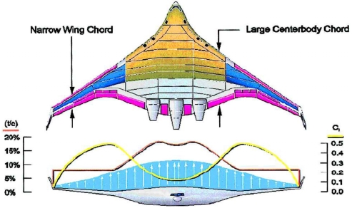
Some insight into the aerodynamic design of the BWB is provided in Fig 4.2, where the trade between wing chord, thickness, and lift coefficient is shown. The outboard wing is moderately loaded, similar to a conventional configuration, where drag is minimized with a balance between the wetted area and shock strength. Moving inboard, the centerbody, with its very large chord, calls for correspondingly lower section lift coefficients to maintain an elliptic span load. The low section lift requirement allows the very thick airfoils for packaging the passenger compartment and trailing-edge reflex for pitch trim.
Navier–Stokes computational fluid dynamics (CFD) methodology in both the inverse design and direct solution modes was employed to define the final BWB geometry. The typical shock on the outboard wing is smeared into a compression wave on the centerbody. The flow pattern on the centerbody remained essentially invariant with angle of attack, and flow separation is initiated in the kink region between the outboard wing and the centerbody. Outer wing flow remains attached, providing lateral control into the stall regime.
Similarly, the flow over the centerbody remains attached and provides a nearly constant flow environment for the engine inlets. This flow behaviour is a consequence of significant lateral flow on the centerbody that provides a three-dimensional relief of compressibility effects. However, the relief on the centerbody is traded for a transonically stressed flow environment in the kink region. This is the ideal span wise location for the stall to begin, from a flight mechanics point of view: The ailerons remain effective, and pitch-up is avoided.
| Are you interested in this topic.Then mail to us immediately to get the full report.
email :- contactv2@gmail.com |
