


Published on Feb 14, 2025
Laser Shot Processing (peening) (LSP) is a surface treatment technology, which consists of irradiating a metallic target with a short and intense laser pulse in order to generate, through high-pressure surface plasma, a plastic deformation and a surface strengthening.
Particular benefit is achieved for improving the fatigue behavior, and the stress corrosion cracking of various materials like austenitic stainless steel in power plants . By now the theoretical aspects of LSP are well elaborated and are widely presented in many publications, which describe physical processes of laser-driven shock wave generation, models of pressure generation, and mechanics of a laser shock interaction with matter.
Meanwhile the experimental conditions of LSP allow one to create considerable changes of the surface morphology of the treated metal in a form of surface structures. Actually a large variety of the surface relief structures were observed with the laser energy higher than the melting threshold for semiconductors and metals. According to their shape these structures could be roughly divided into three groups.
The first group of structures (ripples) is due to the development of the capillary wave instability due to non uniform interference field. The presence of a strong correlation between the parameters of the structures and the characteristics of the laser irradiation allow one to speak about “laser-induced capillary waves .The second group (cellular structures) arises is resulted from instability of capillary waves due to thermal-capillary effects in laser-melted film. The structures mentioned above were obtained at single-shot irradiation conditions. The third group is represented by conical and column microstructures, which are developed during multi-shot irradiation (up to 104 laser shots) .
In this paper the results are presented on the LSP technology application to induce the residual compressive stresses in Inconel 600. To provide reliability of our measurements the results obtained for Inconel 600 are compared to the results obtained under the same experimental conditions for the reference sample (stainless steel 316L), whose mechanical properties are very similar. We also report observation of column-like microstructures tilted in the direction of laser scanning. The light reflected from these conical microstructures is predominantly scattered at angles different from the incidence angle
Metal Improvement Company’s laser-peening system uses a laser energy source that is integrated with a multi-axis robot. These systems communicate to perform highly repeatable and self-correcting laser-peen spot patterns in the areas of concern. A part geometry with the spot pattern that has been optimized for that component. Controls are built into the system such that the energy output for each individual spot is digitally stored according to the part serial number. This allows for a highly traceable quality-control system. When smaller components are processed, they are laser peened with a stationary-beam system. The robot picks up the component and with each shot of the laser, the part is indexed 3-5 mm (depending on spot size) to the next laser-spot location. A secondary robotic arm supplies the flow of water for the tamping layer.
When larger components are processed, they are laser peened with a moveable-beam system. This system uses hardware for tracking and alignment of a laser beam that moves with the robot. Essentially, a stationary laser beam is converted to a moveable laser beam using this configuration. Since the laser beam moves with the robot, moving a large part is not required.
For components that are not practical for shipping, MIC has manufactured a transportable laser-peening system where laser peening can be performed in-situ. A semi-trailer has been custom manufactured to contain all necessary systems to run MIC’s laser-peening technology. The only hook-up required is an electrical supply. Robots are brought to the worksite and the laser energy source is supplied from the laser-peening system located inside the semi-trailer.
Metal Improvement Company is currently approved and is laser peening commercial aerospace components. As of this publication, over 22,000 wide-chord fan blades have been laser peened for jet engines used on commercial, wide-body aircraft. In addition, over 500 fan hubs have been laser peened for use in commercial aerospace. These components are being processed on both stationary beam and moveable beam laser-peening systems.
Laser peening is not a replacement for traditional shot peening, which has solved fatigue failures for 50 years in a cost-effective manner. Laser peening fills an important void by serving fatigue applications that go beyond the current limits of shot peening.
Laser peening is the newest peening technology and has been actively processing parts for industry for over four years. Laser peening also has its own SAE/AMS specification (AMS 2456) and has been ISO9001 and FAA certified. Figure 1 shows a visual comparison of shot peening and laser peening
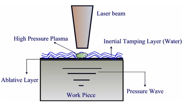
Shot peening uses the shot-stream energy (which consists of the shot mass and velocity) to impart a residual compressive stress into the surface of a metal part. Laser peening directs an intense beam of light to the critical surface. This creates high-pressure plasma that generates a shock wave, driving the compressive stress deep into the surface.
The laser-peening process has unique aspects when compared to shot peening. The first aspect is the surface to be peened is under a laminar flow of water. The water layer is commonly called a tamping layer. Its primary purpose is to act as an inertial stop when the high-pressure plasma is formed. The plasma is formed in nanoseconds and the mass of the water prevents it from expanding, thus driving the energy into the workpiece surface. The second aspect is the use of an ablative layer. Unlike a mask used in shot peening (to prevent surfaces from being hit with shot-peening dimples), an ablative layer is applied in the locations requiring laser peening. The ablative layer acts as a sacrificial layer, preventing a slight burning of the surface that would occur without it.
Shot peening is a random, spray-type process where the surface is showered with a stream of shot media. Laser peening is a CNC-controlled, single-spot process where relatively large spots are placed alongside each other with a slight overlap. Laser spot sizes are typically 3 x 3 mm up to 5 x 5 mm. Laser spots are typically applied at rates of 3-6 Hz depending on component application.
The primary differences on the workpiece from the peening processes are the depth of the residual compressive layer and amount of cold work. Figure 2 shows a comparison of peening-process depths
During LSP treatment we have found that a certain amount of target material is injected into the water due to laser ablation. We analyzed the structure of the ablated material using TEM technique. It is seen that the ablated material is presented in a form of spherical nanopartricles with typical dimension of 60 nm. Such a phenomenon was observed early in the experiments on laser ablation of metals in liquid media. Possible explanation of nanoparticle formation can be given in terms of laser ablation process.
| Are you interested in this topic.Then mail to us immediately to get the full report.
email :- contactv2@gmail.com |
