


Published on Jan 09, 2026
The hydroforming technology has gained in importance over the last few years. Today the lightweight construction of automobiles is one of the main fields of application. This paper gives an overview of the fundamental principles of hydroforming processes and their variants.
The correlations between the work piece geometry and the design of tool and process and the forming result are exemplarily illustrated. Hydroforming is a cost-effective way of shaping malleable metals such as aluminum into lightweight, structurally stiff and strong pieces.
One of the largest applications of hydroforming is the automotive industry, which makes use of the complex shapes possible by hydroforming to produce stronger, lighter, and more rigid unibody structures for vehicles. This technique is particularly popular with the high-end sports car industry and is also frequently employed in the shaping of aluminum tubes for bicycle frames.
Hydroforming is a specialized type of die forming that uses a high pressure hydraulic fluid to press room temperature working material into a die. To hydroform aluminum into a vehicle's frame rail, a hollow tube of aluminum is placed inside a negative mold that has the shape of the desired end result. High pressure hydraulic pistons then inject a fluid at very high pressure inside the aluminum which causes it to expand until it matches the mold. The hydroformed aluminum is then removed from the mold.
Hydro forming is a relatively new process, which uses water pressure to form complex shapes from sheet or tube material. Design studies suggest that automobiles can be made much lighter by using hydro formed components made of steel. Structural strength and stiffness can be improved and the tooling costs reduced because several components can be consolidated into one hydro formed part.
As the automobile industry strives to make car lighter, stronger and more fuel efficient, it will continue to drive hydro forming applications. Some automobile parts such as structural chassis, instrument panel beam, engine cradles and radiator closures are becoming standard hydro formed parts.
The capability of hydro forming can be more fully used to create complicated parts. Using a single hydro formed item to replace several individual parts eliminate welding, holes, punching etc... Hydro forming simplifies assembly and reduce inventory.
Tube hydro forming is a kind of soft-tool forming technology and developed rapidly in the past decades. For taking tubes as processing blanks and liquid as flexible punch, it is more suitable for manufacturing special tubular components, such as different kinds of hollow shafts, discharge pipe of automobile & aero planes, sectional pipes etc..
Tubes were placed in the die and sealed on the end. Then under the co-action of compressive axial force and internal pressure, it is forced to deform from elastic stage to plastic stage. With the increasing of the applied load, the deformation increased correspondingly. Finally, under the extremely high pressure, the tube assumed the internal contour of the die precisely. In tube hydro forming, a cylinder is pressurized internally with 80 to 450 MPa pressure by a fluid like water.
Compared with traditional processing technology, tube hydro forming always manufactures components at one step. So it can enhance part quality, such as tighter tolerance and increase rigidity, and lower production costs and reduction in production cycle. In this method the tube is placed in die and as press clamps the die. Valves, low pressure fluid is introduced into tube to pre forms it.
One the maximum clamping pressure is achieved, the fluid pressure inside the tube is increased so that tube bulges to take internal shape of the die. Simultaneously additional cylinders axially compress the tube to prevent thinning and brushing swing expansion. It is possible that some parts of the component thin excessively during hydro forming. This can sometimes be rectified, in the case of tube hydro forming, by applying axial pressure to feed material into the bulges, thereby reducing bulging.
Tube Hydroforming (THF) has been called with many other names depending on the time and country it was used and investigated. The first industrial applications for this process, namely the production of T-shaped joints, were published in papers in the 1960s; the use of these processes increased rapidly when in 1980sthe automotive industry turned its attention to this process and, more importantly, to the possibilities for light weight constructions. Throughout this paper, THF will be used to describe the metal forming process whereby tubes are formed into complex shapes with a die cavity using internal pressure, which is usually obtained by various means such as hydraulic, viscous medium, elastomers, polyurethane, etc., and axial compressive forces simultaneously.
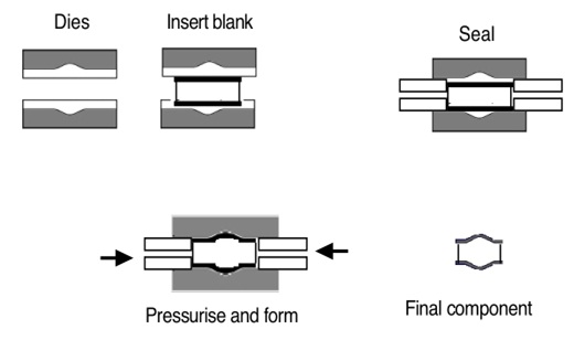
Figure shows the process principles for tube hydroforming. A tube is placed in the tool cavity, whereby the geometry of the die corresponds to the external geometry of the produced part. These tools, in most cases separated in longitudinal direction, are closed by the ram movement of a press, and the tube ends are loaded by two punches moving along the tube axis. Each of the loads applied to the tube ends for sealing the tube’s interior must be at least equal to the force calculated from the product of the tube’s internal area and the tube’s internal pressure.
However, the axial forces may be increased to a higher value if the forming job requires it. Then additional tube wall material is brought into the tool cavity. During the process the internal pressure is increased until the expanding tube wall comes into contact with the inner surface of the die cavity. This process principle may be used for hydroforming both straight and pre-bent tubes.
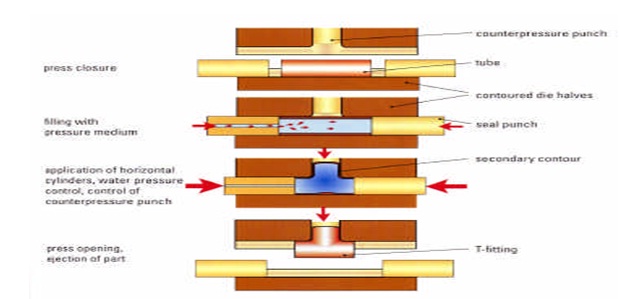
As shown in figure, the applicability of the process implies that failures caused by plastic instabilities such as buckling, folding and bursting can be excluded. The risk of buckling is posed as he start of the process by too high axial loads on the initial tube, and it is also present for the entire starting phase. So that this risk of buckling can be avoided by compensation the unsupported tube lenght with increasing in the section Modulus of the tube cross section through the simultaneous expansion of the tube wall.
In the intake zone of the expansion shape, a formation of folds cannot be avoided; these folds, which are symmetrical to the longitudinal axis, can be reversed by an increase in internal pressure during the final phase of the expansion process. However further folds can occur at the centre of longer expansion forms as a result of too high axial forces: these can be avoided with a proper process controller.
The risk of bursting is a result of too high internal pressure and is initiated by a local neck in the tube wall, whereby the onset of this local necking significantly depends on the initial tube wall thickness. To prevent this risk it must be ensured that the tube wall briefly comes into contact with the wall of the tool at the latest before the onset of necking.
1. Alessia Mentella, “Introduction to hydroforming process”, Università di Cassino.
2. John Godwin “Hydroforming techniques”.
3. Masaaki Mizumura, ET. al. “Development of hydroforming technology”, Nippon steel technical report no.90
4. M, Koç, Ed. By “Hydroforming for advanced manufacturing”, 2009 Woodhead Publishing Limited.
5.www.hydroforming.net
6.www.ultimatehydroforming.com
7. http://www.amalco.com/hydroforming.html
| Are you interested in this topic.Then mail to us immediately to get the full report.
email :- contactv2@gmail.com |
