


Published on Feb 14, 2025
Nanotechnology in mechanical field is the internal combustion engine on a nano scale, which we have chosen as our area of interest. Heat engines have evolved from external combustion engines to internal combustion engines and the hot off the block is the nano internal combustion engine.
The Nano is a 0.1cc (that's less than 0.01 cuin) compression ignition engine - most frequently, if somewhat inaccurately, referred to as a "diesel". It was designed by Richard Gordon and the plans were included as a supplement with the British Magazine Model Engineer in the early 1990's
An idea of the size of the Nano is given by this picture. From backplate to drive washer is less than 1 inch. There are no exotic materials required. The crankcase is hacked from a solid cube of aluminium 3/4" on a side. The piston and contra piston are cast iron. The crankshaft and liner are any old steel from the scrap box
Here is an exploded view of the engine. The odd looking thing in the foreground is a special Nano-Spanner required to tighten the backplate. It also fits the fuel nipple. The construction is extremely conventional - only the scale is unusual
Like all model IC projects, there are a few special jigs and tools required to construct the Nano. All are fully detailed in the plan, which includes step by step instructions with photos. The cutter is made from water hardening drill rod (called "silver steel" in the UK because of its appearance - it contains no silver).the teeth are formed of Dremal-type cut-off wheel
The cutter is used to form the exhaust ports in the cylinder. There are three of these, spaced at 120 degrees with sufficient space between them for the angled transfer ports to slightly overlap the timing. The crown of the piston is conical to assist transfer. The contra piston has a matching concave conical depression.
The venturi is machined separately and secured with Lok-Tite before the final reaming of the crankshaft journal. Notice the three transfer passages in the photo. These terminate in a transfer belt below the cylinder seat that matches with the cylinder transfer ports. If you look very closely, you'll also see the stuff-up that turned away part of the venturi opening.
There's nothing special in the crankshaft components. Another jig (not shown) is made to hold the shaft in the 3-jaw chuck, offset by half the throw for forming the crank pin. Even at these sizes, final lapping to size is no different from larger engines in terms of the amount of metal that must be LEFT for removal. Only the microscopic size makes things difficult. The prop driver knurls were formed with a thread form tool, set on edge and used as a shaper. The prop nut is anodized in the usual way
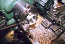
The crankcase starts off as a chunk of aluminum bar of about 1-1/2" diameter, sawn to length, plus a little bit. The first step is to finish turn the front section with a 1/4" radius where the journal blends into the body. The photo shows the roughing out process. Note that the tool is raked back sharply while "hoggin' great cuts" are made so that if it digs in, the cut will be forced shallower, not deeper as it would be if the tool were set raked forward like a regular knife tool.
Next we need to remove all the excess aluminum that does not look like a crankcase. This can easily be done with a band saw, or less easily done with a hacksaw! In either case, marking out is simplified by preparing a full size profile on paper, centred in a circle the same size as the bar stock. Mine was done from the CAD drawings, but pencil and compass could achieve the same result with about the same effort.
The paper template has a hole cut roughly in the middle to accomodate the journal and the blended radius where it meets the front face. It is attached to the face with a standard glue stick. If you're carefull, this will last long enough to complete the butchery. Saw to within about 1/32" (1mm) of the outline. Take care because heat buildup will melt the glue. The next photo shows the four basic stages in crankcase manufacture:
Bar stock blank
Journal turned and sawing template glued in place
Crankcase rough sawn to within 1mm of the template outline
The finished crankcase
In the previous section, the cylinder had progressed to a nearly finished state, still requiring internal lapping. Lapping should always be the last operation on a cylinder of this type. This means the boss for attaching the side port venturi must be fitted before lapping can be done. In this session, the boss is made and the associated parts for the venturi and needle valve.
The boss will be soft soldered to the cylinder (diesels don't get hot enough to melt soft solder). ".solder does not make the joint, it only keeps the air out" and schooled me to make a good fit of parts to be soldered. The boss will butt to the cylinder, which has an outside diameter of 0.500". So, a good fit can be achieved by profiling the boss with a 1/2" end mill. In this photo, we see the boss blank (enough for four) which has been finished outside, drilled ready for tapping and transferred still in the 3 jaw chuck to the mill for end profiling
Nano ic engine has various applications ranging from race cars to space crafts.
In race cars this IC Nano Engine was used. The engine was fully fabricated, that is, no castings were employed.
It can be controlled in aero planes/satellites/space ships etc., the timing of in let and exhaust valves.
According to NASA reports they are experimenting about the use of nano engine in nano & pico satellites.
In case of a mine tragedy where harmful gases are emitted ,these nano ic engines can be employed as powerful blowers to blow out these gases is a less time saving the lives of trapped miners .We require atleast 5-6 blowers to blow these gases where as two nano ic engines could do the tick in less time.
Agriculture pumps sets.
Every field of industry.
The problem Every day people are spending more and more money because of rising gas prices. People all over the world are trying to find a solution—even visiting websites to locate the nearest and cheapest gas, all the while losing time and mileage just to reach [these] refueling stations. Many have been giving up favorite hobbies and changing life plans because of the need to reallocate their funds for gas.
For those of us who must drive to work or school, it seems we have little choice but to continue paying more. Now, there is a way to fight back against these constant increases in gas prices—and to fight pollution and protect the environment in the process.
Use the most advanced technology available to improve fuel economy, prolong the engine life, reduce harmful emissions and protect the environment. The number one product for fuel economy, power and pollution control is now available .
Introducing our two unique nanotechnology products:
F2-21 NanoLube Engine Oil Tratment, and
F2-21 NanoRon Gas & Diesel Fuel Enhancer.
With nanotechnology, fuel transforms at the nano-level to achieve a more complete combustion, resulting in increased fuel economy, more driving power, and fewer pollutive emissions.
Use either product or both to get multiple benefits:
- Adds great power to your engine. NanoLube eases heavy driving loads and increases
driving pleasure with a faster, smoother, and quieter ride.
- Boosts miles per gallon (analogous to buying Premium Gas or boosting your octane number),
while saving you money and conserving energy.
- Prolongs engine life by cleaning your combustion chamber and piston ring deposits,
extending engine life and cutting equipment downtime.
- Protects the environment by reducing harmful emissions and fighting global warming.
| Are you interested in this topic.Then mail to us immediately to get the full report.
email :- contactv2@gmail.com |
