


Published on Apr 02, 2024
The Dynamic Speed Governor is a system that can be implemented effectively for an efficient and perfectly controlled traffic system. This system can limit the speed of a moving vehicle over an area where the speed has to be restricted and retained within a predetermined value. The Dynamic Speed Governor consists of mainly two parts, the Transmitter section and the Receiver section.
The transmitter section is mounted on the signal board, on which the speed limit over that area is indicated. Receiver section is kept inside the vehicle. The radio frequency signal from the transmitter is transmitted and the receiver receives it. If the speed of the vehicle is greater than the speed limit proposed for that particular area, which in turn is transmitted by the transmitter section, the speed governor comes into action and restricts the driver from going beyond that rated speed.
If the system detects that the speed of the vehicle has gone beyond the speed limit, a signal is generated from the dynamic speed governor circuit. This signal in turn is used to drive the mechanical part of the vehicle, which closes the fuel nozzle of the vehicle thereby restricting the vehicle from going beyond that speed.
Dynamic speed governor is designed with the aim of dynamically limiting the speed of the vehicle to a preset value, when the driver drives through an area that has a preset speed limit, thereby encouraging safe driving and preventing accidents. The main idea is to transmit the speed limit for the area to the vehicle, as it approaches an area that has speed restriction, so that the driver can be warned and the speed of the vehicle is automatically reduced. The system is implemented with the help of a RF transmitter that transmits a speed limit to the approaching vehicle, and an RF receiver inside the vehicle that accepts the incoming signal and then feeds the speed limit as one of the inputs to a comparator. The other input of the comparator comes from a digital tachometer.
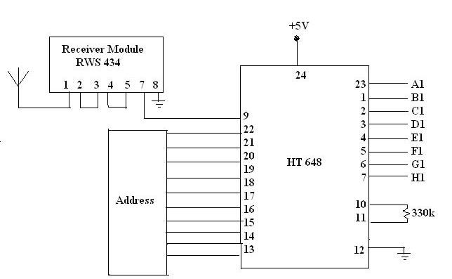
The RF receiver unit consists of a receiver section and a display section.In the receiver unit, receiver module receives the transmitted signal. Receiver module contains crystal oscillator. Frequency of receiver module is 434MHz.Receiver module does not contain any antenna. But it has dipoles, which can act as antenna leads. Receiver module receives the serial data. We want to convert the serial data into parallel form.
So the serial data is given to HT 648 IC.IT is a serial to parallel encoder, which converts serial data into parallel form for proper use. This parallel data is given to 4511 IC.4511 is a Seven segment display encoder, which converts the data into digital form. The transmitted speed is displayed in the BCD to 7-segment display unit.
A comparator unit compares the received set reference speed or the speed set for that particular zone with the actual speed of the user vehicle. If the speed of the user vehicle is greater than that of the reference speed received, the comparator pin 13 outputs goes high and this high output is used to trigger the alarm section. The comparator unit is realized by using CD 4585, which is a 4-bit comparator.
However the speed of the vehicle and the received speed limit exceeds 4 bits when converted into the binary system. Hence two CD 4585 comparator IC’s are cascaded so as to implement an 8-bit comparator. Comparator IC’s in 2 steps does comparison. The Ist IC compares the most significant output and the output from the Ist is then fed to the 2ndIC.The 2nd IC then compares the lower 4 bits and the output from this IC is used to drive the alarm unit.
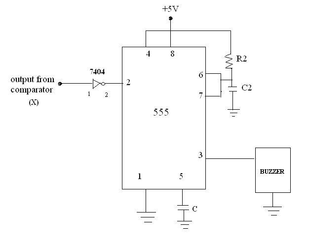
The aim of the project is to warn the user when he is exceeding the speed limit of the zone. Here, we make use of a buzzer that will sound an alarm when the user vehicle is exceeding the set speed limit. The output from the comparator pin received set speed limit. This output is then given to a 555 timer IC that is connected in the monostable mode of operation through a 7404 IC (NOT gate).
Whenever the output from the comparator is low the input to the 555 will be high and hence it out operate. However when the output at the comparator IC goes high it will appear as a zero at the pin2 of the 555 timer IC i.e., less than 1/3Vcc.The zero input to the IC being less than 1/3Vcc will trigger the monoshot and a square pulse of the preset period 5 seconds will be obtained at the output pin. The square pulse will trigger the buzzer which will produce a warning signal for 5 seconds thereby warning the over speeding users. The use of a monoshot in between the buzzer and the comparator IC prevents the continuous ringing of the buzzer thereby avoiding distraction and promoting safe warning for the users.
This section consists of a sensor part, 555Timer circuits counter ICs and display unit. There is a motor, which is connected to a shaft and is placed in relation with the sensor circuit. The rotation of the motor can generate pulses, which can be converted into speed in km/hr.
| Are you interested in this topic.Then mail to us immediately to get the full report.
email :- contactv2@gmail.com |
