


Published on Jan 09, 2026
Distributed generation is one of the important field of research now a days. Market prospect for microturbine for distributed power generation and their associated high grade heat extremely encouraging. Therefore microturbines are becoming a point of study.
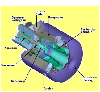
Presented paper tries to discus the microturbine concept, technology description gives technical and practical background through basic process and thermodynamic cycle. Various components of microturbine and their performance is briefly analyzed.
To improve this characteristics and efficiency the points like development of chemically recuperated gas turbine is added. Microturbine economics is a big question .Fuel used for microturbine gives list of all possible fuel to be used. Manufacturers and availability of microturbine is one important discussed point. Application gives idea about customer range, customer targeted stand by power, hybrid electric vehicles, CHP operation, etc. At the end conclusion is drawn for the feasibility study of microturbine .
Microturbines operate on the same thermodynamic cycle, known as the Brayton cycle, as larger gas turbines. In this cycle, atmospheric air is compressed, heated, and then expanded, with the excess power produced by the expander (also called the turbine) over that consumed by the compressor used for power generation. The power produced by an expansion turbine and consumed by a compressor is proportional to the absolute temperature of the gas passing through those devices.
Consequently, it is advantageous to operate the expansion turbine at the highest practical temperature consistent with economic materials and to operate the compressor with inlet airflow at as low a temperature as possible. Higher temperature and pressure ratios result in higher efficiency and specific power. Thus, the general trend in gas turbine advancement has been towards a combination of higher temperatures and pressures. However, microturbine inlet temperatures are generally limited to 1,800ºF or below the use of relatively inexpensive materials for the turbine wheel, and to maintain pressure ratios at a comparatively low 3.5 to 4.0. Turbo-Compressor Package
The heart of the microturbine is the compressor-turbine package, which is commonly mounted on a single shaft along with the electric generator. Two bearings support the single shaft. The single moving part of the one-shaft design has the potential for reducing maintenance needs and enhancing overall reliability. There are also two-shaft versions, in which the turbine on the first shaft directly drives the compressor while a power turbine on the second shaft drives a gearbox and conventional electrical generator producing 60 Hz power. The two shaft design features more moving parts but does not require complicated power electronics to convert high frequency AC power output to 60 Hz.
Moderate to large-size gas turbines use multi-stage axial flow turbines and compressors, in which the gas flows along the axis of the shaft and is compressed and expanded in multiple stages. However, microturbine turbo machinery is based on single-stage radial flow compressor and turbines. Rotary vane and scroll compression are the most commonly used technology in the microturbine industry. Second generation gas compressor technologies are in development or being introduced. That may reduce costs and target on-board application Rotary vane compression technology offers a wide range of gaseous fuel flexibility Parasitic loads vary based on type of gas and inlet pressures available, general rule 4 to 6% for natural gas and 10 to 15% for bio gas.
The microturbine produces electrical power either via a high-speed generator turning on the single turbo-compressor shaft or with a separate power turbine driving a gearbox and conventional 3,600 rpm generator. The high-speed generator of the single-shaft design employs a permanent magnet (typically Samarium-Cobalt) alternator, and requires that the high frequency AC output (about 1,600 Hz for a 30 kW machine) be converted to 60 Hz for general use. This power conditioning involves rectifying the high frequency AC to DC, and then inverting the DC to 60 Hz AC.
Power conversion comes with an efficiency penalty (approximately five percent).To start-up a single shaft design, the generator acts as a motor turning the turbo-compressor shaft until sufficient rpm is reached to start the combustor. Full start-up requires several minutes. If the system is operating independent of the grid (black starting), a power storage unit (typically a battery UPS) is used to power the generator for start-up.
| Are you interested in this topic.Then mail to us immediately to get the full report.
email :- contactv2@gmail.com |
