


Published on Apr 02, 2024
A strain gauge (also strain gage) is a device used to measure the strain of an object. Invented by Edward E. Simmons and Arthur C. Ruge in 1938, the most common type of strain gauge consists of an insulating flexible backing which supports a metallic foil pattern. The gauge is attached to the object by a suitable adhesive, such as cyanoacrylate. As the object is deformed, the foil is deformed, causing its electrical resistance to change.
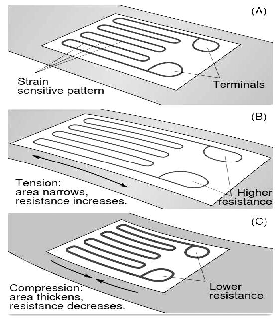
A strain gauge takes advantage of the physical property of electrical conductance and its dependence on the conductor's geometry. When an electrical conductor is stretched within the limits of its elasticity such that it does not break or permanently deform, it will become narrower and longer, changes that increase its electrical resistance end-to-end. Conversely, when a conductor is compressed such that it does not buckle, it will broaden and shorten, changes that decrease its electrical resistance end-to-end. From the measured electrical resistance of the strain gauge, the amount of applied stress may be inferred.
A typical strain gauge arranges a long, thin conductive strip in a zig-zag pattern of parallel lines such that a small amount of stress in the direction of the orientation of the parallel lines results in a multiplicatively larger strain over the effective length of the conductor than would be observed with a single straight-line conductive wire. Strain gauges measure only local deformations and can be manufactured small enough to allow a "finite element" like analysis of the stresses to which the specimen is subject.
An excitation voltage is applied to input leads of the gauge network, and a voltage reading is taken from the output leads. Typical input voltages are 5 V or 12 V and typical output readings are in millivolts.
Foil strain gauges are used in many situations. Different applications place different requirements on the gauge. In most cases the orientation of the strain gauge is significant.
Gauges attached to a load cell would normally be expected to remain stable over a period of years, if not decades; while those used to measure response in a dynamic experiment may only need to remain attached to the object for a few days, be energized for less than an hour, and operate for less than a second.
Strain gauges are attached to the substrate with a special glue. The type of glue depends on the required lifetime of the measurement system. For short term measurements (up to some weeks) cyanoacrylic glue is appropriate, for long lasting installation epoxy glue is required. Usually epoxy glue requires high temperature curing (at about 80-100°C). The preparation of the surface where the strain gauge is to be glued is of the utmost importance. The surface must be smoothed (e.g. with very fine sand paper), deoiled with solvents, the solvent traces must then be removed and the strain gauge must be glued immediately after this to avoid oxidation or pollution of the prepared area. If these steps are not followed the strain gauge binding to the surface may be unreliable and unpredictable measurement errors may be generated.
Variations in temperature will cause a multitude of effects. The object will change in size by thermal expansion, which will be detected as a strain by the gauge. Resistance of the gauge will change, and resistance of the connecting wires will change.
Most strain gauges are made from a constantan alloy. Various constantan alloys and Karma alloys have been designed so that the temperature effects on the resistance of the strain gauge itself cancel out the resistance change of the gauge due to the thermal expansion of the object under test. Because different materials have different amounts of thermal expansion, self-temperature compensation (STC) requires selecting a particular alloy matched to the material of the object under test.
Strain gauges that are not self-temperature-compensated (such as isoelastic alloy) can be temperature compensated by use of the dummy gauge technique. A dummy gauge (identical to the active strain gauge) is installed on an unstrained sample of the same material as the test specimen. The sample with the dummy gauge is placed in thermal contact with the test specimen, adjacent to the active gauge. The dummy gauge is wired into a Wheatstone bridge on an adjacent arm to the active gauge so that the temperature effects on the active and dummy gauges cancel each other.
Zero Offset - If the impedance of the four gauge arms are not exactly the same after bonding the gauge to the force collector, there will be a zero offset which can be compensated by introducing a parallel resistor to one or more of the gauge arms.
Temperature coefficient of Gauge Factor (TCGF) - This is the change of sensitivity of the device to strain with change in temperature. This is generally compensated for by the introduction of a fixed resistance in the input leg, whereby the effective supplied voltage will increase with temperature, compensating for the decrease in sensitivity with temperature.
EMI induced errors - As strain gauges output voltage is in the mV range, even uV if the Wheatstone bridge voltage drive is kept low to avoid self heating of the element, special care must be taken in output signal amplification to avoid amplifing also the superimposed noise. A solution which is frequently adopted is to use "carrier frequency" amplifiers which convert the voltage variation into a frequency variation (as in VCOs) and have a narrow bandwidth thus reducing out of band EMI.
Simple mechanical types (such as illustrated to the left) are used in civil engineering to measure movement of buildings, foundations, and other structures. In the illustrated example, the two halves of the device are rigidly attached to the foundation wall on opposite sides of the crack. The red reference lines are on the transparent half and the grid is on the opaque white half. Both vertical and horizontal movement can be monitored over time. In this picture, the crack can be seen to have widened by approximately 0.3 mm (with no vertical movement) since the gauge was installed.
| Are you interested in this topic.Then mail to us immediately to get the full report.
email :- contactv2@gmail.com |
