


Published on Nov 30, 2023
The project is a 3D LED CUBE DISPLAY (8x8x8 PIXELS) which displays different patterns stored in the microcontroller. This LED cube is like a LED screen, but it is special in that it has a third dimension, making it 3D. Think of it as many transparent low resolution displays. In normal displays it is normal to try to stack the pixels as close as possible in order to make it look better, but in a cube one must be able to see through it, and more spacing between the pixels (actually it's voxels since it is in 3d) is needed. The spacing is a trade-off between how easy the layers behind it are seen, and voxel fidelity. Since it is a lot more work making a LED cube than a LED display, they are usually low resolution. A LED display of 8x8 pixels are only 64 LEDs, but a LED cube in 8x8x8 is 512 LEDs, an order of magnitude harder to make! This is the reason LED cubes are only made in low resolution.
A LED cube does not have to be symmetrical; it is possible to make a 7x8x9, or even oddly shaped ones. Here we have an 8x8x8 shaped one. The code is written in the C language using AVR studio and it is burned into the ARDUINO using the pony prog 2000.The circuit needs to be mounted on the mechanical structure or platform where it displays the patterns that are stored in the arduino as indicated in the codes. The patterns are displayed on a 3D structure which is made up of stainless steel rods. The messages can be changed as per user need by rewriting the arduino in-built memory. The complete display system circuit is power supply run on 5V, 2A which is provided externally. This unique way of displaying messages is a very eye catching; therefore its uses can in the field of advertising, toys, etc.
3D LED CUBE is a evolution from 2D DISPLAY. Before this, 2D DISPLAY is usually used in many electronic devices to display something. After that, 3D takes a part on the electronic technology world. The first era of 3D LED CUBE is built the 3x3x3 pocket led. It just use 27 led to shown some text display or interactive design. The cube's 3D construction is straightforward and easy to solder using the included jig and instructions. With use 27 led’s, the design or text that display is not too clear. It runs using a PIC16F690 and a piece of software written in VB.NET. After that, 4x4x4 LED CUBE has been introduced. 64 led’s has been used to show the 3D view. Many type of controller can be used to develop this project. PCB is one of the controller that been used.
For example, Atmel Atmega16 microcontroller and AVR microcontroller. Each LED can be addressed individually in software, enabling it to display amazing 3d animations. On the programming side, many type of coding can be built for this project such as FPGA, mat lab and c language. Now 8x8x8 3D LED CUBE with 512 led’s has been choose for this project. It has two ways can be choose as controller for this project or by arduino controller board .Have a same concept, but with a different works. C language with hex files will be use to run the program. The reason why will choose C language because it related with microcontroller interfacing subject that had been taken for all electric and electronic student. It will be use as a software to run this program. This unique way of displaying messages is a very eye catching and much more stand out compared to the two dimensional normal panel displays.
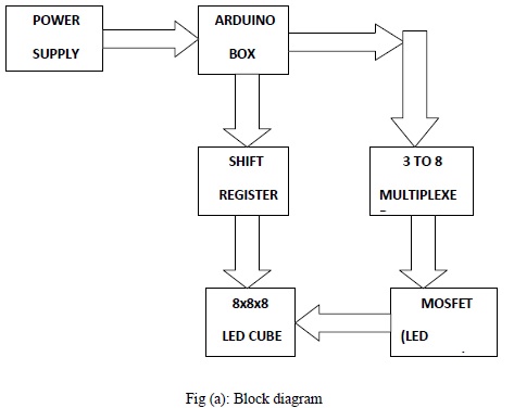
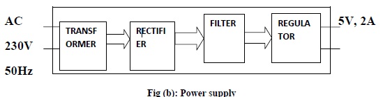
Power supply is used to provide a +5 volt, 2A from 230V 50Hz ac supply with the use of bridge rectifier and regulator.
Arduino uno is a microcontroller board based on the ATmega328P. It has 14 digital input/output pins(of which 6 can be used as PWM outputs),6 analog inputs , 16 MHz quartz crystal, a USB connection , a power jack ,an ICSP header and a reset button. It contains everything needed to support the microcontroller; simply connect it to a computer with a USB cable or power it with a AC to DC adapter or a battery to get started.
IRFZ44 is an N-channel (MOSFET) enhancement mode standard level field-effect power transistor in a plastic envelope using ‟trench‟ technology. The device features very low on-state resistance and has integral zener diodes giving ESD protection up to 2kV. It is intended for use in switched mode power supplies and general purpose switching applications.
The 74HC/HCT573 are high-speed Si-gate CMOS devices and are pin compatible with low power Schottky TTL (LSTTL). They are specified incompliance with JEDEC standard no.7A.The 74HC/HCT573 are octal D-type transparent latches featuring separate D-type inputs for each latch and 3-state outputs for bus oriented applications. A latch enable (LE) input and an output enable (OE) input are common to all latches.
This 3D led cube is made up of stainless steel rods with 512 led‟s. There are 64 anodes 8 cathodes. The LED cube is made up of columns and layers. The cathode legs of every LED in a layer are soldered together. All the anode legs in one column are soldered together. Each of the 64 columns is connected to the controller board with a separate wire. Each column can be controlled individually. Each of the 8 layers also has a separate wire going to the controller board. Each of the layers is connected to a transistor that enables the cube to turn on and off the flow of current through each layer.
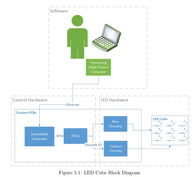
The highest level description of the 3D LED cube includes only it’s most general components. Figure 5.1 describes this by listing the signal flow from the user input to the visual LED output. After the user inputs a command into the software, via a GUI, the software will communicate the details of the animation to the embedded processor on one of the PCBs. The embedded processor will control the on-board FPGA, which will operate the row and column circuitry to update the animation on the LED cube frame-by-frame. Figure 5.1 shows this signal flow of the 3D LED cube at the system level.
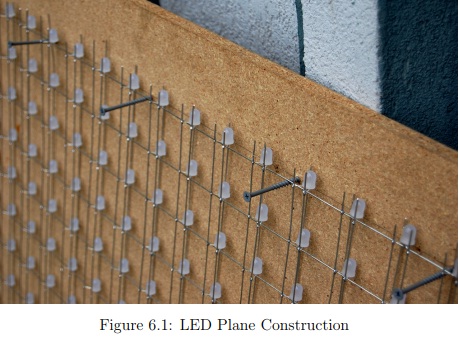
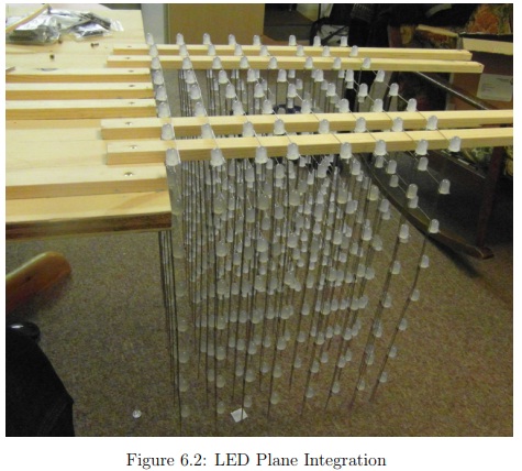
The construction of the LED cube will be completed in several stages. The cube itself, or the actual 1000 LEDs and their wiring/structure, will be completed plane-by-plane. Each plane of LEDs will be soldered to their respective joints made up of 10x10 crossing pieces of 18 gauge pre-tinned copper wire, carefully spaced based upon the required pitch of 6mm. The spacing will be accomplished by building the plane flat, on a panel of plywood. Screws will be placed in the plywood to direct the spacing of the 18 gauge wire. This stage of construction is illustrated in Figure 6.1. The LEDs will be soldered to the wire plane structure over the plywood. Finally, upon the completion and testing of a panel, the panel will be integrated into the other panels, one by one, to form the cube. This will be accomplished by placing long, thin pieces of plywood off the side of a bench, the wood steadily secured with screws to the bench. Each plane of wire and LEDs will then be slid perpendicularly over the pieces of wood sticking out of the bench. As the planes will hang securely upon this wooden jig, the placing between planes can also be precisely controlled. It is from this position that the 10x10x10 LED cube will then be attached to the base of the cube. This stage of the design is illustrated in Figure 6.2.
The base of the cube will be built separately, approximately 2.5ft W x 2.5ftL x 1ft H. It will also be built with plywood, secured together with screws. The control hardware will be stored inside the base of the cube, and connected through the base to the LED cube structure.
LED cube is like a LED screen, but it is special in that it has a third dimension, making it 3D. Think of it as many transparent low resolution displays. In normal displays it is normal to try to stack the pixels as close as possible in order to make it look better, but in a cube one must be able to see trough it, and more spacing between the pixels (actually it's voxels since it is in 3d) is needed. The spacing is a trade-off between how easy the layers behind it are seen, and voxel fidelity. Since it is a lot more work making a LED cube than a LED display, they are usually low resolution. A LED display of 8x8 pixels are only 64 LEDs, but a LED cube in 8x8x8 is 512 LEDs, an order of magnitude harder to make! This is the reason LED cubes are only made in low resolution. A LED cube does not have to be symmetrical; it is possible to make a 7x8x9, or even oddly shaped ones.
This LED cube has 512 LEDs. Obviously, having a dedicated IO port for each LED would be very impractical. Thus there comes the need of a micro controller with 512 IO ports, and run 512 wires through the cube. Instead, LED cubes rely on an optical phenomenon called persistence of vision (POV). When a led is flashed really fast, the image will stay on the retina for a little while after the led turns off. By flashing each layer of the cube one after another really fast, it gives the illusion of a 3d image, when in fact we are looking at a series of 2d images stacked onto one another. This is also called multiplexing. With this setup, there exists the need of only 64 (for the anodes) + 8 (for each layer) IO ports to control the LED cube. There are anodes, cathodes, columns and layers, for this led cube.
In order to light up an LED, we have to run current from the anode to the cathode. The LED cube is made up of columns and layers. The cathode legs of every LED in a layer are soldered together. All the anode legs in one column are soldered together. Each of the 64 columns is connected to the controller board with a separate wire. Each column can be controlled individually. Each of the 8 layers also has a separate wire going to the controller board. Each of the layers is connected to a transistor that enables the cube to turn on and off the flow of current through each layer. By only turning on the transistor for one layer, current from the anode columns can only flow through that layer. The transistors for the other layers are off, and the image outputted on the 64 anode wires are only shown on the selected layer. To display the next layer, simply turn off the transistor for the current layer, change the image on the 64 anode wires to the image for the next layer. Then turn on the transistor for the next layer. Rinse and repeat very fast.
The layers will be referred to as layers, cathode layers or ground layers. The columns will be referred to as columns, anode columns or anodes.
The control unit is quite simple, 3 ports of the Mega32 were used:
one port controls 8 FETs for sinking the 8 ground layers
one port is wired to all 8 8bit d-latch inputs
the last port is used to enable the d-latch inputs
Since the d-latches are only able to sink or source 70mA on all 8 latches, we had to limit the diode current to ~9mA, which is fairly enough for this type of LED.
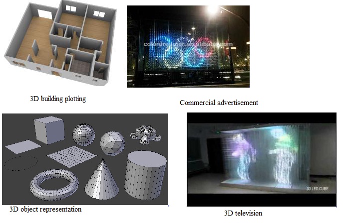
3D building plotting
Commercial advertisement
3D object representation
3D television
It is compact and hence uses less area coverage
It can be displayed clearly in dark room as well as well lighted rooms/outside conditions
It has efficient power management
Project is heavily hardware oriented
Time constrains
The research stage of the senior design project led to a number of important decisions - choosing parts as well as noticing and planning ahead for potential design concerns. When the design was completed and documented, we had a clear and functional outline: a software interface to send instructions to an on-board control PCB, containing an embedded processor and FPGA operating in unison to control two separate driver boards containing LED drivers and MOSFETs which in turn modulated the current to each individual LED with a high level of speed and precision. A detailed testing procedure confirms the operation of the 3D LED cube - leaving the group with a clear and finalized path moving forward.
The most substantial result of this documentation was the learning experience of the individual group members. This senior design project took it’s members well beyond their formal classroom electrical and computer engineering experience. Although the skill development was broad-based, including time management, team building, communication, and technical writing, the primary growth came from achieving the goal of this project: establishing a functional 3D LED cube prototype design. This success accompanied the new skills and knowledge obtained such as embedded processor development, discrete component integration, printed circuit board construction, communication protocols, embedded software development, and software design. Clearly this project spanned several topics covering the topics of both electrical and computer engineering. The group members look forward past the successful completion of this stage of development, to the completion of a physical functional prototype to be built in the secondary phase of this senior design project.
We were successful in completing our mini project “3D LED CUBE DISPLAY (8x8x8 Pixels)”. It was a wonderful experience as we attained basic knowledge on different steps in circuit manufacturing such as circuit testing and debugging, soldering components, PCB fabrication etc that will surely help us in our career in electronics field. By doing this project we also came to know about the advantages and disadvantages of our project and its future development. Today we have a 3D world; a 3D revolution will be formed in the upcoming years. This project can be upgraded to a great extent by suitable add-ons and we expect a bright future for our project in the coming years. The main applications of our project include toys, advertisements, study material, research purposes etc.
[1] P. Salmon, M. Regan, and I. John-ston. Human error and road transport.Monash University, 2005. Available 31stMarch 2008: http://www.monash.edu.au/muarc/reports/muarc257.pdf. (PDF) A review of automotive infrared pedestrian detection techniques. Available from: https://www.researchgate.net/publication/224384040_A_review_of_automotive_infrared_pedestrian_detection_techniques [accessed Dec 06 2018].
[2] Pedestrian Safety. Irish Road Safety Au-thority, 2005. Available 31st March 2008:http://www.rsa.ie/publication/publication/upload/pedestrian safety.doc.
[3] Y. Fang, K. Yamada, Y. Ninomiya, B. Horn,and I. Masaki. Comparison betweeninfrared-image-based and visible-image-basedapproaches for pedestrian detection. In Pro-ceedings IEEE Intelligent Vehicles Sympo-sium, pages 505–510, 2003. (PDF) A review of automotive infrared pedestrian detection techniques. Available from: https://www.researchgate.net/publication/224384040_A_review_of_automotive_infrared_pedestrian_detection_techniques [accessed Dec 06 2018].
