


Published on Apr 02, 2024
Green technology is related to technological advances made in the field of power generation from non conventional energy source that are considered to be environmentally friendly and non polluting. Every form of energy collection will result in some pollution but those that are green are known to cause less than those that are not. Green house gases ,a byproduct of traditional sources of energy such as fossil fuels are said to be causing global warming at an accelerated pace and hence there is a need to focus on technology that is environmentally friendly and also economically feasible. The United Nations Energy Organization tags fossil fuels as elimentary energy/conventional energy.
Electricity is merely a secondary energy derived from these sources. At present the energy consumed all over the world relies mainly on five main energy sources like coal,petroleum,natural gas,water and nuclear energy. The consumption of petroleum constitutes approximately 60% of energy used from all sources.
Statistics show that daily consumption of petroleum is 40 million barrels of which 50% is for automobile use.In accordance with this calculation,as fuels are burnt poisonous materials such as 500 million tonnes of carbon monoxide,100 million tonnes of hydrocarbons,550 million tonnes of carbon and 50 million tonnes of nitrogen oxides are emitted into atmosphere every year causing Green House Effect.
First generation technologies are most competitive in locations with abundant resources.Their future depends on exploration of available resource potential particularly in developing countries and on overcoming challenges related to environment and social acceptance. Example:-hydroelectric plants,geo thermal power plants and biomass briquettes.
Second generation technologies are said to be the future of power generation and is fast catching up but the market for these sources are limited to only a few countries.Example:- solar heating systems,use of ethanol,etc.
Third generation technologies are not yet widely demonstrated or commercialised.They are on the horizon and may have potentional comparable to other renewable energy technologies but still depend on attracting suffecient attention and R&D funding.Ex: SOLAR POWER TOWERS
Green technology is the future of this society. It's main goal is to find ways to produce technology in ways that do not damage or deplete the Earth's natural resources.
In addition to not depleting natural resources, green technology is meant as an alternative source of technology that reduces fossile fuels and demonstrates less damage to human, animal, and plant health, as well as damage to the world, in general.
Next, green technology is so that products can be re- used and recycled. The use of green technology (clean technology) is supposed to reduce the amount of waste and pollution that is created during production and consumption. The most important and urgent concern and want for green technology is for energy purposes. We need better, more efficient was to produce energy without burning all the world's coal and using all the world's fossil fuels and natural resources.
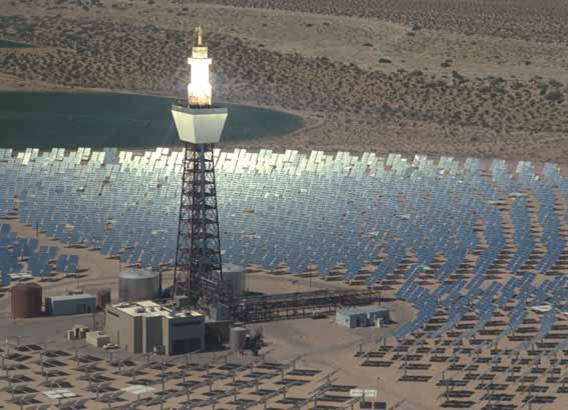
• Solar power towers also known as Concentrated Solar Power (CSP) Towers generate electric power from sunlight by focusing concentrated solar radiation on tower mounted heat exchangers.
• The system uses hundreds to thousands of sun-tracking mirrors called heliostats to reflect the incident sunlight onto the receiver.
• These plants are best suited for utility-scale applications in the 30 to 400 MW range.
• The limited supply of fossil hydrocarbon resources and the negative impact of CO2 emissions on the global environment dictate the increasing usage of renewable energy sources.
• Concentrated Solar Power (CSP) is the most likely candidate for providing the majority of this renewable energy, because it is amongst the most cost-effective renewable electricity technologies and because its supply is not restricted if the energy generated is transported from the world's solar belt to the population centres.
• In power tower systems, heliostats (A Heliostat is a device that tracks the movement of the sun which is used to orient a mirror of field of mirrors, throughout the day, to reflect sunlight onto a target-receiver) reflect and concentrate sunlight onto a central tower-mounted receiver where the energy is transferred to a HTF.
• This energy is then passed either to the storage or to power-conversion systems, which convert the thermal energy into electricity.
Heliostat field, the heliostat controls, the receiver, the storage system, and the heat engine, which drives the generator, are the major components of the system.
For a large heliostat field , a cylindrical receiver has advantages when used with Rankine cycle engines, particularly for radiation from heliostats at the far edges of the field.
Cavity receivers with larger tower height to heliostat field area ratios are used for higher temperatures required for the operation of turbines.
These plants are defined by the options chosen for a HTF, for the thermal storage medium and for the power-conversion cycle. HTF may be water/steam, molten nitrate salt, liquid metals or air and the thermal storage may be provided by PCM (phase change materials) or thermally insulating materials.. Power tower systems usually achieves concentration ratios of 300–1500, can operate at temperatures up to 1500o C.
To maintain constant steam parameters even at varying solar irradiation, two methods can be used:
Integration of a fossil back-up burner; or
Utilization of a thermal storage as a buffer
By the use of thermal storage, the heat can be stored for few hours to allow electricity production during periods of peak need, even if the solar radiation is not available.
Examples of heliostat based power plants:
• The 10 MWe Solar One and Solar Two demonstration projects in the Mojave Desert, which have now been decommissioned.
• The above 10 MW Solar Tres Power Tower in Spain builds on these projects. In Spain the 11 MW PS10 Solar Power Tower was recently completed.
• In South Africa, a solar power plant is planned with 4000 to 5000 heliostat mirrors, each having an area of 140 m².
Major parts of solar tower are –
1)Heliostats
2)Central Receiver
3)Molten Salt
4)Steam Generator
Heliostats are reflective surfaces or mirrors which track the suns rays and reflect it onto the central receiver. Relatively few heliostats have been manufactured to date, and their cost is high (>$250/m2). As the demand for solar power increases, heliostat mass production methods will be developed that will significantly reduce their cost.
Research is currently being conducted under the Solar Manufacturing Technology (SolMaT) Initiative to develop low-cost manufacturing techniques for early commercial low volume builds. Prices are a strong function of annual production rate.

Since the heliostat field represents the largest single capital investment in a power tower plant, advancements in technology are needed to improve the ability to manufacture, reduce costs, and increase the service life of heliostats.
In particular, a lower cost azimuth drive system is needed (i.e., to rotate the heliostat around an axis that is perpendicular to the ground).
Recent Developments in Heliostat designs:
The modern R&D efforts have focused on polymer reflectors and stretched-membrane heliostats.
A stretched-membrane heliostat consists of a metal ring, across which two thin metal membranes are stretched.
A focus control system adjusts the curvature of the front membrane, which is laminated with a silvered-polymer reflector, usually by adjusting the pressure in the plenum between the two membranes.
Central receiver (or power tower) systems use a field of distributed mirrors – heliostats – that individually track the sun and focus the sunlight on the top of a tower.
By concentrating the sunlight 600–1000 times, they achieve temperatures from 800°C to well over 1000°C.
• The central receiver is also called high-tech heat exchanger which sits atop a tower. The central receiver heats molten salt at around 250°C, pumped from a “cold” storage tank, to 565°C, where it flows to a “hot” tank for storage.
• When the grid load dispatcher decides electricity is needed from the plant, hot salt is pumped to a steam generating system that produces superheated steam for a turbine/generator.
• The salt then is returned to the cold tank, where it is stored and eventually reheated in the receiver to complete the cycle.
• Smaller, simpler receivers are needed to improve efficiency and reduce maintenance. Advanced receiver development currently underway, under the SolMaT Initiative, includes consideration of new steel alloys for the receiver tubes and ease of manufacture for the entire receiver subsystem. Panels of these new receiver designs were initially tested at Solar Two.
(MOLTEN SALT STORAGE SYSTEM)
Molten nitrate salt, though an excellent thermal storage medium, can be a troublesome fluid to deal with because of its relatively high freezing point (220oC/428ºF). To keep the salt molten, a fairly complex heat trace system must be employed. (Heat tracing is composed of electric wires attached to the outside surface of pipes. Pipes are kept warm by way of resistance heating.) Problems were experienced during the startup of Solar Two due to the improper installation of the heat trace. Though this problem has been addressed and corrected, research is needed reduce the reliance on heat tracing in the plant.
This could be accomplished by one or more of the following options:
(1) develop a salt “anti-freeze” to lower the freezing point,
(2) identify and/or develop components that can be “cold started” without preapplication of the heat trace, or
(3) develop thermal management practices that are less reliant on heat trace.
Within the Solar Two project, the third option will be explored. If it is unsuccessful, the other two options should be pursued. Also, valves can be troublesome in molten-salt service. Special packings must be used, oftentimes with extended bonnets, and leaks are not uncommon. Furthermore, freezing in the valve or packing can prevent it from operating correctly. While today’s valve technology is adequate for molten-salt power towers, design improvements and standardization would reduce risk and ultimately reduce O&M costs.
The salt storage medium is a mixture of 60 percent sodium nitrate and 40 percent potassium nitrate. It melts at 220ºC(428ºF) and is maintained in a molten state (290ºC/554ºF) in the ‘cold’ storage tank. Molten salt can be difficult to handle because it has a low viscosity (similar to water) and it wets metal surfaces extremely well.
The energy storage system for Solar Two consists of two 875,000 liter storage tanks which were fabricated on-site by Pitt-Des Moines. The tanks are externally insulated and constructed of stainless steel and carbon steel for the hot and cold tanks, respectively. Thermal capacity of the system is 110 MWh . A natural convection cooling system is used in the foundation of each tank to minimize overheating and excessive dehydration of the underlying soil.
The steam generator design selected for the Solar Two project is completely different than the prototype tested at Sandia Laboratories during the technology development activity of the 1980’s for Solar One because of change in heat transfer fluid. The recirculating-drum-type system tested at Sandia performed well. However, at Solar Two, a kettle-boiler design was selected in an attempt to reduce cost. Significant problems have been encountered with this new system during the startup phase at Solar Two, requiring a redesign in many areas. Depending on the success of implementing the design changes, it was considered appropriate to reevaluate the optimum steam generator design before proceeding to the first commercial plant.
Solar One, which operated from 1982 to 1988, was the world’s largest power tower plant. It proved that large-scale power production with power towers was feasible. In that plant, water was converted to steam in the receiver and used directly to power a conventional Rankine-cycle steam turbine.
The heliostat field consisted of 1818 heliostats of 39.3 m2 reflective area each. The project met most of its technical objectives by demonstrating -
(1) the feasibility of generating power with a power tower,
(2) the ability to generate 10 MW for eight hours a day on summer solstice and four hours a day during winter solstice.
During its final year of operation, Solar One’s availability during hours of sunshine was 96% and its annual efficiency was about 7%. (Annual efficiency was relatively low because of the plant’s small size and the inclusion of non-optimized subsystems.)
The Solar One thermal storage system stored heat from solar-produced steam in a tank filled with rocks and sand using oil as the heat-transfer fluid. The system extended the plant’s power-generation capability into the night and provided heat for generating low-grade steam for keeping parts of the plant warm during off-hours and for morning startup.
Unfortunately, the storage system was complex and thermodynamically inefficient. While Solar One successfully demonstrated power tower technology, it also revealed the disadvantages of a water/steam system, such as the intermittent operation of the turbine due to cloud transcience and lack of effective thermal storage.
During the operation of Solar One, research began on the more advanced molten-salt power tower design . This development culminated in the Solar Two project.
| Are you interested in this topic.Then mail to us immediately to get the full report.
email :- contactv2@gmail.com |
