


Published on Apr 02, 2024
KERS means Kinetic Energy Recovery System and it refers to the mechanisms that recover the energy that would normally be lost when reducing speed. The energy is stored in a mechanical form and retransmitted to the wheel in order to help the acceleration. Electric vehicles and hybrid have a similar system called Regenerative Brake which restores the energy in the batteries.The device recovers the kinetic energy that is present in the waste heat created by the car’s braking process. It stores that energy and converts it into power that can be called upon to boost acceleration.
There are principally two types of system - battery (electrical) and flywheel (mechanical). Electrical systems use a motor-generator incorporated in the car’s transmission which converts mechanical energy into electrical energy and vice versa. Once the energy has been harnessed, it is stored in a battery and released when required.
Mechanical systems capture braking energy and use it to turn a small flywheel which can spin at up to 80,000 rpm. When extra power is required, the flywheel is connected to the car’s rear wheels. In contrast to an electrical KERS, the mechanical energy doesn’t change state and is therefore more efficient.
There is one other option available - hydraulic KERS, where braking energy is used to accumulate hydraulic pressure which is then sent to the wheels when required.
The first, mechanical, consisted of using a carbon flywheel in a vacuum linked via a CVT transmission to the differential. This system stores the mechanical energy, offers a big storage capacity and has the advantage of being independent from the gearbox. However, to be driven precisely, it requires some powerful and bulky actuators, and lots of space.
Compared to the alternative of electrical-battery systems, the mechanical KERS system provides a significantly more compact, efficient, lighter and environmentally-friendly solution.
The components within each variator include an input disc and an opposing output disc. Each disc is formed so that the gap created between the discs is ‘doughnut’ shaped; that is, the toroidal surfaces on each disc form the toroidalcavity. Two or three rollers are located inside each toroidal cavity and are positioned so that the outer edge of each roller is in contact with the toroidal surfaces of the input disc and output disc. As the input disc rotates, power is transferred via the rollers to the output disc, which rotates in the opposite direction to the input disc.
The angle of the roller determines the ratio of the Variator and therefore a change in the angle of the roller results in a change in the ratio. So, with the roller at a small radius (near the centre) on the input disc and at a large radius (near the edge) on the output disc the Variator produces a ‘low’ ratio. Moving the roller across the discs to a large radius at the input disc and corresponding low radius at the output produces the ‘high’ ratio and provides the full ratio sweep in a smooth, continuous manner.
The transfer of power through the contacting surfaces of the discs and rollers takes place via a microscopic film of specially developed long-molecule traction fluid. This fluid separates the rolling surfaces of the discs and rollers at their contact points.
The input and output discs are clamped together within each variator unit. The traction fluid in the contact points between the discs and rollers become highly viscous under this clamping pressure, increasing its ‘stickiness’ and creating an efficient mechanism for transferring power between the rotating discs and rollers.
The second option, electrical, was to rely on an electrical motor, which works by charging the batteries under braking and releasing the power on acceleration. This system consists of three important parts:
1. An electric motor (MGU: Motor Generator Unit) situated between the fuel tank and the engine, linked directly to the crankshaft of the V8 to deliver additional power.
2. Some latest generation ion-lithium batteries (HVB: High Voltage Battery Pack) capable of storing and delivering energy rapidly.
3. A control box (KCU: KERS Control Unit), which manages the behavior of the MGU when charging and releasing energy. It is linked to the car’s standard electronic control unit.
In essence a KERS systems is simple, you need a component for generating the power, one for storing it and another to control it all. Thus KERS systems have three main components: The MGU, the PCU and the batteries. They are simply laid out as in the diagram below:
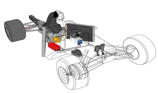
Schematic Assembly Of KERS in a F1 car
The FIA (Federation InternationaleL"Automobile) have authorized hybrid drivetrains in Formula 1 racing for the 2009 racing season. The intent is to use the engineering resources of the Formula 1 community to develop hybrid technology for use not only in motorsport but also eventually in road vehicles. The hybrid systems specifications have been kept to a minimum, especially the type of hybrid system. This was done purposely to lead to the study and development of various alternatives for electrical hybrids which has been met with success.
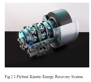
The Flybrid Kinetic Energy Recovery System (KERS) was a small and light device designed to meet the FIA regulations for the 2009 Formula One season.
The key system features were:
• A flywheel made of steel and carbon fibre that rotated at over 60,000 RPM inside an evacuated chamber
• The flywheel casing featured containment to avoid the escape of any debris in the unlikely event of a flywheel failure
• The flywheel was connected to the transmission of the car on the output side of the gearbox via several fixed ratios, a clutch and the CVT
• 60 kW power transmission in either storage or recovery
• 400 kJ of usable storage (after accounting for internal losses)
• A total system weight of 25 kg
• A total packaging volume of 13 litres
The layout of the device was tailored exactly to meet the customer's requirement resulting in a truly bespoke solution that fitted within the tight packaging constraints of a F1 car.
The mechanical KERS system utilises flywheel technology developed by Flybrid Systems to recover and store a moving vehicle’s kinetic energy which is otherwise wasted when the vehicle is decelerated.
With a focus on safety, the FIA have specified a limit on both the power rating of the hybrid system at 60kW and the quantity of energy transfer per lap at 400kJ. This translates into an extra 85bhp for just under seven seconds, which makes overtaking another vehicle on the track easier and the race much more interesting.Thus although a 0.3s boost to laptimes, the system was ultimately limited in its potential to improve laptimes.
Thus no team could create a competitive advantage from a more powerful system. Then the weight of the system created issues, At a time when the wider front slick tyres demanded an extreme weight distribution of up to 49% weight on the front axle, the 25+Kg of a KERS system mounted behind the Centre of gravity, the handicapped teams being able to push weight forwards. Most teams dropping or not racing their system cited weight as the main reason for its loss.
The 60kW/400kJ limits in Formula 1 will not apply to road cars. Road cars will safely have more power and energy transfer due to their larger weight when compared with racecars, which will provide them with significant benefits. There is more than one type of KERS used in motorsports. The most common is the electronic system built by the Italian company MagnetiMarelli, which is used by Red Bull, Toro Rosso, Ferrari, Renault and Toyota. Although races have been won with this technology, KERS was removed from the 2010 Formula 1 season due to its high cost.
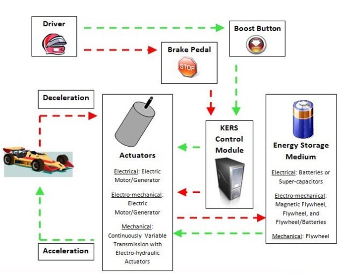
Sensors:boost button, brake sensor
Actuators:electric motor/generator unit, continuously variable transmission, flywheel, electro-hydraulic system, clutch.
Data Communications:CAN Bus.
Manufacturers:Bosch Motorsport, Flybrid Systems, MagnetiMarelli, Williams Hybrid Power, Zytek Group
Since kinetic energy is the energy of motion, you could probably guess that cars create lots of it. Capturing some of that kinetic energy for the sake of fuel efficiency in a hybrid car is a little tricky, but regenerative braking is one common method employed by many automakers.
On a non-hybrid car during a routine stop, mechanical braking slows and then stops the vehicle. For instance, if your vehicle has disc brakes, the brake pads clamp down on a rotor to stop the car. If your car has drum brakes, the brake shoe pushes the brake lining material outward toward the brake drum surface to slow or stop the car. In both cases, most of the kinetic energy in the spinning wheels is absorbed by the pads or the drums, which creates heat.
On a hybrid car that uses regenerative braking, the electric motor is used to slow the car. When the motor is operating in this mode, it acts as a generator to recover the rotational kinetic energy at the wheels, convert it into energy and store it in the car's batteries. When the driver of the hybrid car takes his or her foot off of the accelerator pedal, the resistance provided by the generator slows the car first and then the mechanical brake pads can be applied to finish the job. Of course, the mechanical brake pads can also be engaged immediately in an emergency braking scenario.
The car uses the energy stored in the battery to power the electric motor which drives the car at low speeds. Depending on the type of hybrid, the electric motor can either work alone to move the car or it can work in concert with the car's gasoline-powered engine. So regenerative braking, coupled with eco-friendly driving techniques like slow starts and slower overall vehicle speeds, is an important feature on some of some of the most fuel-efficient vehicles on the road today.
Regenerative brakes may seem very hi-tech, but the idea of having "energy-saving reservoirs" in machines is nothing new. Engines have been using energy-storing devices called flywheels virtually since they were invented.
The basic idea is that the rotating part of the engine incorporates a wheel with a very heavy metal rim, and this drives whatever machine or device the engine is connected to. It takes much more time to get a flywheel-engine turning but, once it's up to speed, the flywheel stores a huge amount of rotational energy. A heavy spinning flywheel is a bit like a truck going at speed: it has huge momentum so it takes a great deal of stopping and changing its speed takes a lot of effort. That may sound like a drawback, but it's actually very useful. If an engine (maybe a steam engine powered by cylinders) supplies power erratically, the flywheel compensates, absorbing extra power and making up for temporary lulls, so the machine or equipment it's connected to is driven more smoothly.
By adopting the cheaper and lighter flywheel system (the ideal solution if it could be made to fit into the no-refueling era cars), a more powerful boost, and limiting the number of activations in a race it would cover all the bases it needs to. It would be affordable for the all the teams, deliver performances as well as being a more interesting race variable. The sidepod solution is quite unique, and has given us a new envelope to try to drive performance to the rear of the car. We need to keep thinking out-of-the-box. Compared to ten or 20 years ago, it's really quite staggering what can be delivered given the restrictions we have now – it's a tribute to imaginative thinking
Thus we are coming to the end of the elaborate study of KERS going through their advantaged limitation relevance and finally to the modification. To sum up this seminar we have gone through sophisticated concept which will surely be much raved in coming days.
Also it would be a great showcase of technology which could have a major impact on the car industry in years to come. In the future the technology could also be used on buses, trains, and wind power generation.
1. www.howstuffworks.com/KERS.htm
2. www.wikipedia.org/wiki/Kinetic_Energy_Recovery_Systems
3. www.flybridsystems.com/F1System.html
4. www.ferrari.com/KERS/HY-KERS-Experimental-Vehicle.aspx
5. www.scarbsf1.wordpress.com/2010/10/20/kers-anatomy
6. www.wired.com/autopia/2010/10/flywheel-hybrid-system-for-premium-vehicles
7. www.gizmag.com/mechanical-kers-technology-for-road-cars
| Are you interested in this topic.Then mail to us immediately to get the full report.
email :- contactv2@gmail.com |
