


Published on Apr 02, 2024
A clutch is a mechanism for transmitting rotation, which can be engaged and disengaged. Clutches are useful in devices that have two rotating shafts. In these devices, one shaft is typically driven by motor or pulley, and other shaft drives another device. The clutch connects the two shafts so that they can either be locked together and spin at the same speed (engaged), or be decoupled and spin at different speeds (disengaged).
The clutch disc (centre) spins with the flywheel (left). To disengage, the lever is pulled (black arrow), causing a white pressure plate (right) to disengage the green clutch disc from turning the drive shaft, which turns within the thrust-bearing ring of the lever. Never will all 3 rings connect, with any gaps.
Electromagnetic clutches operate electrically, but transmit torque mechanically. This is why they used to be referred to as electro-mechanical clutches.
A horseshoe magnet has a north and south pole. If a piece of carbon steel contacts both poles, a magnetic circuit is created. In an electromagnetic clutch, the north and south pole is created by a coil shell and a wound coil. In a clutch, when power is applied, a magnetic field is created in the coil. This field (flux) overcomes an air gap between the clutch rotor and the armature. This magnetic attraction, pulls the armature in contact with the rotor face. The frictional contact, which is being controlled by the strength of the magnetic field, is what causes the rotational motion to start.
The torque comes from the magnetic attraction, of the coil and the friction between the steel of the armature and the steel of the clutch rotor. For many industrial clutches, friction material is used between the poles. The material is mainly used to help decrease the wear rate, but different types of material can also be used to change the coefficient of friction (torque for special applications). For example, if the clutch is required to have an extended time to speed or slip time, a low coefficient friction material can be used and if a clutch is required to have a slightly higher torque (mostly for low rpm applications), a high coefficient friction material can be used.
In a clutch, the electromagnetic lines of flux have to pass into the rotor, and in turn, attract and pull the armature in contact with it to complete clutch engagement. Most industrial clutches use what is called a single flux, two pole design. Mobile clutches of other specialty electromagnetic clutches can use a double or triple flux rotor. The double or trip flux refers to the number of north/south flux paths, in the rotor and armature.
This means that, if the armature is designed properly and has similar banana slots, what occurs is a leaping of the flux path, which goes north south, north south. By having more points of contact, the torque can be greatly increased. In theory, if there were 2 sets of poles at the same diameter, the torque would double in a clutch. Obviously, that is not possible to do, so the points of contact have to be at a smaller inner diameter. Also, there are magnetic flux losses because of the bridges between the banana slots. But by using a double flux design, a 30%-50% increase in torque, can be achieved, and by using a triple flux design, a 40%-90% in torque can be achieved. This is important in applications where size and weight are critical, such as automotive requirements.
The coil shell is made with carbon steel that has a combination of good strength and good magnetic properties. Copper (sometimes aluminium) magnet wire, is used to create the coil, which is held in shell either by a bobbin or by some type of epoxy/adhesive.
To help increase life in applications, friction material is used between the poles on the face of the rotor. This friction material is flush with the steel on the rotor, since if the friction material was not flush, good magnetic traction could not occur between the faces. Some people look at electromagnetic clutches and mistakenly assume that, since the friction material is flush with the steel that the clutch has already worn down but this is not the case. Clutches used in most mobile applications, (automotive, agriculture, construction equipment) do not use friction material. Their cycle requirements tend to be lower than industrial clutches, and their cost is more sensitive. Also, many mobile clutches are exposed to outside elements, so by not having friction material, it eliminates the possibility of swelling (reduced torque), that can happen when friction material absorbs moisture.
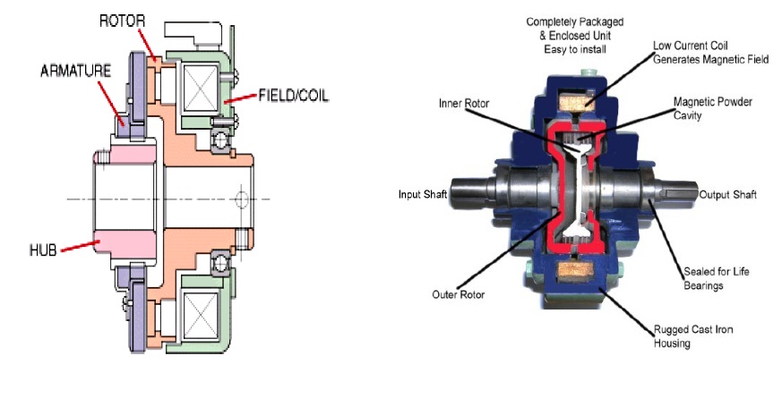
The clutch has four main parts: field, rotor, armature, and hub (output) . When voltage is applied the stationary magnetic field generates the lines of flux that pass into the rotor. (The rotor is normally connected to the part that is always moving in the machine.) The flux (magnetic attraction) pulls the armature in contact with the rotor (the armature is connected to the component that requires the acceleration), as the armature and the output start to accelerate. Slipping between the rotor face and the armature face continues until the input and output speed is the same (100% lockup). The actual time for this is quite short, between 1/200th of a second and 1 second.
Disengagement is very simple. Once the field starts to degrade, flux falls rapidly and the armature separates. One or more springs hold the armature away from the rotor at a predetermined air gap.
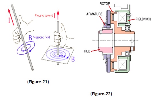
• The clutch has four main parts: field, rotor, armature, and hub (output) (Figure-22). When voltage is applied the stationary magnetic field generates the lines of flux that pass into the rotor. (The rotor is normally connected to the part that is always moving in the machine.) The flux (magnetic attraction) pulls the armature in contact with the rotor (the armature is connected to the component that requires the acceleration), as the armature and the output start to accelerate. Slipping between the rotor face and the armature face continues until the input and output speed is the same (100% lockup). The actual time for this is quite short, between 1/200th of a second and 1 second.
• Disengagement is very simple. Once the field starts to degrade, flux falls rapidly and the armature separates. One or more springs hold the armature away from the rotor at a predetermined air gap.
• Voltage/current - and the magnetic field
• If a piece of copper wire was wound, around the nail and then connected to a battery, it would create an electro magnet. The magnetic field that is generated in the wire, from the current, is known as the “right hand thumb rule”. (FIGURE-21) The strength of the magnetic field can be changed by changing both wire size and the amount of wire (turns). EM clutches are similar; they use a copper wire coil (sometimes aluminum) to create a magnetic field.
• The fields of EM clutch can be made to operate at almost any DC voltage, and the torque produced by the clutch or brake will be the same, as long as the correct operating voltage and current is used with the correct clutch. If a 90 V clutch, a 48 V clutch and a 24 V clutch, all being powered with their respective voltages and current, all would produce the same amount of torque. However, if a 90 V clutch had 48 V applied to it, this would get about half of the correct torque output of that clutch. This is because voltage/current is almost linear to torque in DC electromagnetic clutches.
• A constant power supply is ideal if accurate or maximum torque is required from a clutch. If a non regulated power supply is used, the magnetic flux will degrade, as the resistance of the coil goes up. Basically, the hotter the coil gets the lower the torque will be, by about an average of 8% for every 20°C. If the temperature is fairly constant, but there may not be enough service factor in your design for minor temperature fluctuation. Over-sizing, the clutch would compensate for minor flux. This will allow the use a rectified power supply which is far less expensive than a constant current supply.
• Based on V = I × R, as resistance increases available current falls. An increase in resistance, often results from rising temperature as the coil heats up, according to: Rf = Ri × [1 + αCu × (Tf - Ti)] Where Rf = final resistance, Ri = initial resistance, αCu = copper wire’s temperature coefficient of resistance, 0.0039 °C-1, Tf = final temperature, and Ti = initial temperature.
There are actually two engagement times to consider in an electromagnetic clutch. The first one is the time that it takes for a coil to develop a magnetic field, strong enough to pull in an armature. Within this, there are two factors to consider. The first one is the amount of ampere turns in a coil, which will determine the strength of a magnetic field. The second one is air gap, which is the space between the armature and the rotor. Magnetic lines of flux diminish quickly in the air.. Air gap is an important consideration especially with a fixed armature design because as the unit wears over many cycles of engagement the armature and the rotor will create a larger air gap which will change the engagement time of the clutch. In high cycle applications, where registration is important, even the difference of 10 to 15 milliseconds can make a difference, in registration of a machine. Even in a normal cycle application, this is important because a new machine that has accurate timing can eventually see a “drift” in its accuracy as the machine gets older.
The second factor in figuring out response time of a clutch is actually much more important than the magnet wire or the air gap. It involves calculating the amount of inertia that the clutch needs to accelerate. This is referred to as “time to speed”. In reality, this is what the end-user is most concerned with. Once it is known how much inertia is present for the clutch to start then the torque can be calculated and the appropriate size of clutch can be chosen.
Most CAD systems can automatically calculate component inertia, but the key to sizing a clutch is calculating how much inertial is reflected back to the clutch or brake. To do this, engineers use the formula: T = (wk2 × ΔN) / (308 × t) Where T = required torque in lb-ft, WK2 = total inertia in lb-ft2, ΔN = change in the rotational speed in rpm, and t = time during which the acceleration or deceleration must take place.
There are also online sites that can help confirm how much torque is required to accelerate a given amount of inertia over a specific time.
Having designed and constructed the circuit it was felt that it met all of the given specifications although there were still a number of improvements that could have been made. These improvements have been covered briefly in the discussion section and given more time they could have been implemented in the circuit. As already mentioned the only specifications not met were that on start-up the machine should rotate for 3 seconds in one direction before braking and reversing. Using the clutch method mentioned in the discussions could solve this but the design brief given did not extend to cover the drum so has not been included in the final design.
During the course of the project a number of other points became evident which greatly ease the process of designing an electronic circuit. Simulation using a computer package such as Pspice saves a considerable amount of time by allowing the circuit to be easily laid out and tested. Any changes required can be made easily without disturbing the rest of the circuit. Another advantage of Pspice is the ability to produce graphs of the outputs from the circuit, which can then be scaled, formatted and printed as required. To do this for the actual circuit requires very specialised and expensive equipment.
In conclusion, the group felt that all objectives had been met and that the final circuit was successful in fulfilling its role. A number of important lessons were learned about the problems involved in designing a circuit to meet a real-world need and ways of overcoming these problems were found.
[1] Schematic Capture with Microsim Pspice Herniter Prentice Hall 3 Ed. Rd P250-252
[2] http://www.emclab.umr.edu/ An Introduction to EMC University of Missouri-Rolla EMC laboratory
[3] http://reality.sgi.com/csp/scvemc/emcdef.html Ensuring Compatibility Between the Electromagnetic Environment and Electric and Electrical Devices Kimball William, Chairman, IEEE EMC Education Committee
[4] http://www.howstuffworks.com/gears.htm How gears Work
| Are you interested in this topic.Then mail to us immediately to get the full report.
email :- contactv2@gmail.com |
