


Published on Apr 02, 2024
A Full wave rectifier is a circuit arrangement which makes use of both half cycles of input alternating current (AC) and converts them to direct current (DC). In our tutorial on Half wave rectifiers, we have seen that a half wave rectifier makes use of only one-half cycle of the input alternating current. Thus a full wave rectifier is much more efficient (double+) than a half wave rectifier. This process of converting both half cycles of the input supply (alternating current) to direct current (DC) is termed full wave rectification.
Full wave rectifier can be constructed in 2 ways. The first method makes use of a centre tapped transformer and 2 diodes. This arrangement is known as Center Tapped Full Wave Rectifier.
The second method uses a normal transformer with 4 diodes arranged as a bridge. This arrangement is known as a Bridge Rectifier.
To construct a full wave bridge rectifier and show that that Alternating Current is rectified into a Direct Current.
The process of converting AC (which periodically reverses direction) current into DC (which flows only in one direction) current is known as Rectification.
The electrical device used to so is known as Rectifier.
Rectifiers have many uses, but are often found serving as components of DC power supplies and high-voltage direct current power transmission systems. Rectification may serve in roles other than to generate direct current for use as a source of power.
The simple process of rectification produces a type of DC characterized by pulsating voltages and currents (although still unidirectional). Depending upon the type of end-use, this type of DC current may then be further modified into the type of relatively constant voltage DC characteristically produced by such sources as batteries and solar cells.
A diode bridge is an arrangement of four (or more) diodes in a bridge circuit configuration that provides the same polarity of output for either polarity of input. When used in its most common application, for conversion of an alternating current (AC) input into a direct current (DC) output, it is known as a bridge rectifier. A bridge rectifier provides full-wave rectification from a two-wire AC input, resulting in lower cost and weight as compared to a rectifier with a 3-wire input from a transformer with a center-tapped secondary winding.
Connecting wires
Step-down transformer
Diodes (4)
Capacitor (1)
LED (1)

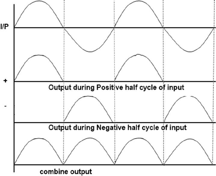
Initially when the A.C. is supplied to the transformer, it steps down the 220V main supply to 6 volts. It has a capability of delivering a current of 500mA. The 6 volts A.C. appearing across the secondary coil is the RMS value and the peak value is 8.4 volts. During the Ist half cycle of the A.C. input Diode D1 is forward biased and a current ‘I’ flows in the circuit in the direction ABCDEFGHIJKLM. During this time diodes D2 and D3 are reverse biased. So they do not conduct any electric current.
During the next half cycle the diode D2 is forward and D1 is reversed. Hence D2 conducts current in the direction MLKJCDEFGHIA and D1 does not conduct any current.
In subsequent half cycles of the A.C current the above processes are repeated. In both the half cycles it is clear that current flows through LED in only one direction.
Even though the voltage across LED is unidirectional it will still contain a few A.C components. This is filtered and made smooth using a capacitor, which filters 99% of the A.C current.
Capacitor nearly filters all A.C components from the supply. But there will be slight factor of A.C. current still left in the output but it is negligible. The output Direct Current and voltage light up the LED.
Because of their low cost compared to center tapped they are widely used in power supply circuit.
This can be used to detect the amplitude of modulated radio signal.
Bridge rectifiers can be used to supply polarized voltage in welding.
In daily life, rectifier find use in mobile chargers.
The rectification efficiency of full-wave rectifier is double of that of a half-wave rectifier.
The ripple voltage is low and of higher frequency in case of a full-wave rectifier so simple filtering circuit is required.
Higher output voltage higher output power and higher TUF in case of a full-wave rectifier.
In a full-wave rectifier, there is no problem due to DC saturation of the core because the DC currents in the two halves of the transformer secondary flow in opposite directions.
Full-wave rectifier needs more circuit elements and is costlier.
The output voltage of the full wave rectifier is not constant, it is always pulsating. But this cannot be used in real life applications. In other words, we desire a DC power supply with a constant output voltage. In order to achieve a smooth and constant voltage a filter with a capacitor or an inductor is used.
Physics – Textbook for class XII (NCERT)
Laboratory Manual of Physics
Encyclopedias
www.google.in
www.wikipedia.org
www.youtube.com
