


Published on Apr 02, 2024
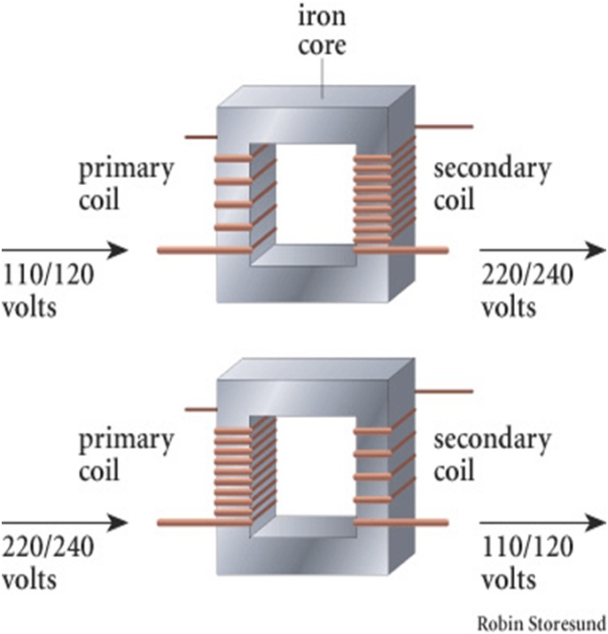
A transformer is an electrical device which is used for changing the A.C. voltages. A transformer is most widely used device in both low and high current circuit. As such transformers are built in an amazing strength of sizes. In electronic, measurement and control circuits, transformer size may be so small that it weight only a few tens of grams where as in high voltage power circuits, it may weight hundred of tones.
In a transformer, the electrical energy transfer from one circuit to another circuit takes place without the use of moving parts. A transformer which increases the voltages is called a step-up transformer. A transformer which decreases the A.C. voltages is called a step-down transformer. Transformer is, therefore, an essential piece of apparatus both for high and low current circuits.
To investigate the relation between:
i) Output and input voltage
ii) Number of turns in the secondary coil and primary coil of a self designed transformer
When an altering e.m.f. is supplied to the primary coil p1p2, an alternating current starts falling in it. The altering current in the primary produces a changing magnetic flux, which induces altering voltage in the primary as well as in the secondary. In a good-transformer, whole of the magnetic flux linked with primary is also linked with the secondary, then the induced e.m.f. induced in each turn of the secondary is equal to that induced in each turn of the primary. Thus if Ep and Es be the instantaneous values of the e.m.f.’s induced in the primary and the secondary and Np and Ns are the no. of turns of the primary secondary coils of the transformer and
Dфь / dt = rate of change of flux in each turnoff the coil at this instant,
we have
Ep = -Np dфь/dt ----------------- (1) and
Es = -Ns dфь/dt ----------------- (2)
Since the above relations are true at every instant, so by dividing 2 by 1, we get
Es / Ep = - Ns / Np ----------------(3)
As Ep is the instantaneous value of back e.m.f induced in the primary coil p1, so the instantaneous current in primary coil is due to the difference (E – Ep ) in the instantaneous values of the applied and back e.m.f. further if Rp is the resistance o, p1p2 coil, then the instantaneous current Ip in the primary coil is given by
Ip = E – Ep / Rp
E – Ep = Ip Rp
When the resistance of the primary is small, Rp Ip can be neglected so therefore
E – Ep = 0 or Ep = E
Thus back e.m.f = input e.m.f
Hence equation 3 can be written as
Es / Ep = Es / E = output e.m.f / input e.m.f = Ns / Np = K
Where K is constant, called turn or transformation ratio.
In a step up transformer
Es > E so K > 1, hence Ns > Np
In a step down transformer
Es < E so K < 1, hence Ns < Np
If
Ip = value of primary current at the same instant t
And
Is = value of sec. current at this instant, then
Input power at the instant t = Ep Ip and
Output power at the same instant = Es Is
If there are no losses of power in the transformer, then
Input power = output power
Or
Ep Ip = Es Is
Or
Es / Ep = Ip / Is = K
In a step up transformer
As k > 1, so Ip > Is or Is < Ip
i.e. current in sec. is weaker when secondary voltage is higher.
Hence, whatever we gain in voltage, we lose in current in the same ratio.
Similarly it can be shown, that in a step down transformer, whatever we lose in voltage, we gain in current in the same ratio.
Thus a step up transformer in reality steps down the current & a step down transformer steps up the current.
Efficiency of a transformer is defined as the ratio of output power to the input power. i.e.
η = output power / input power = Es Is / Ep Ip
Thus in an ideal transformer, where there is no power losses, η = 1. But in actual practice, there are many power losses; therefore the efficiency of transformer is less than one.
• Iron rod
• Copper wire
• Voltmetre
• Ammetre
A Transformer based on the Principle of mutual induction according to this principle, the amount of magnetic flux linked with a coil changing, an e.m.f is induced in the neighbouring coil that is if a varying current is set-up in a circuit induced e.m.f. is produced in the neighboring circuit. The varying current in a circuit produce varying magnetic flux which induces e.m.f. in the neighboring circuit.
The transformer consists of two coils. They are insulated with each other by insulated material and wound on acommon core. For operation at low frequency, we may have asoft iron. The soft iron core is insulating by joining thin ironstrips coated with varnish to insulate them to reduce energy losses by eddy currents.The input circuit is called primary. And the output circuit is called secondary.
i) Demonstrating the principle of transformer by winding primary and secondary coil on a steel rod
1. Take a soft iron rod of cm and cm diameter. Wrap thick paper on it.
2. Wind a coil P of enameled copper wire 200 turns.
3. Wind another coil S of thick enameled copper wire with 400 turns.
4. Both coils are wound over same length of the rod, so that almost the entire flux produced by current in one is linked to the other.
5. Connect the coil S with an AC voltmeter. Connect an identical voltmeter across P also.
6. Switch on the current in P and note voltage across the two coils
7. Find the ratio Vp to Vs
1. We will find that ratio of Vp and Vs across the two coils is equal to the ratio of number of turns in the coil P to that in the coil S.i.e.,
Vp/Vs = Np/Ns ---------------(1)
2. The coil P (to which AC voltage is applied) is
Called the primary and coil S (in which AC is induced) is called the secondary.
3. Since coil S is placed very close to the coil P,the power in the primary is transferred into the secondary through mutual induction.
4. It is clear from equation 1, that by appropriate choice of the turn ratio i.e., Np/Ns, we can obtain a higher voltage or lower voltage in S compared to that in P.
Following are the major sources of energy loss in a transformer:
It is the energy loss in the form of heat in the copper coils of a transformer. This is due to joule heating of conducting wires.
It is the energy loss in the form of heat in the iron core of the transformer. This is due to formation of eddy currents in iron core. It is minimized by taking laminated cores.
It occurs inspite of best insulations. Therefore, rate of change of magnetic flux linked with each turn of S1S2 is less than the rate of change of magnetic flux linked with each turn of P1P2.
It is the loss of energy due to repeated magnetization and demagnetization of the iron core when A.C. is fed to it.
It is the humming noise of a transformer
A transformer is used in almost all a.c. operations
In voltage regulator for T.V., refrigerator, computer, air conditioner etc.
A step down transformer is used for welding purposes.
A step down transformer is used for obtaining large current.
A step up transformer is used for the production of X-Rays and NEON advertisement.
Transformers are used in voltage regulators and stabilized power supplies.
Transformers are used in the transmissions of a.c. over long distances.
Small transformers are used in Radio sets, telephones, loud speakers and electric bells etc.
1. The output voltage of the transformer across the secondary coil depends upon the ratio (Ns/Np) with respect to the input voltage
2. The output voltage of the transformer across the secondary coil depends upon the ratio (Ns/N p) with respect to the input voltage
3. There is a loss of power between input and output coil of a transformer.
1) NCERT textbook class 12
2) NCERT physics lab Manuel
3) INTERNET
4) www.yahoo.com
5) www.scribd.com
6) www.google.com
