


Published on Apr 02, 2024
A laser alarm system operates by projecting a beam of invisible laser light across a doorway or window opening. When the light is broken, it activates a buzzer or alarm. The principles are very similar to those of lower tech burglar alarms. A laser alarm requires only slightly more sophisticated electronics and can be put together by anyone with a soldering gun and a knack for tinkering with basic circuits and transistors.
To make and study the functions of a Laser Security System.
This system for security uses the combination of LASER light and LDR. The LDR module has an onboard potentiometer to adjust the sensitivity of LDR, so that it only senses laser light falling onto it. The concept is quite simple and similar to what we see in movies where antique, priceless ornaments are protected under laser lights. As someone crosses these lights, an alarm runs on to indicate unauthorised presence. This project works similarly. In normal conditions, where there is always laser light falling on the LDR, the LDR module always gives a high signal to microcontroller. When someone crosses this laser light, it will behave as an obstruction between the LDR module and laser light, resulting in no light falling on LDR. In such cases LDR module gives a low signal to the microcontroller, which indicates it to switch on an alarm
• Electric buzzer
• LDR(Light Dependent Resistance)
• Breadboard
• 10k ohm Resistor
• 9V Battery
• Laser
• Connecting Wires
• Transistor

1. Take the breadboard and mark its two extreme sides , any one as positive and other as negative.
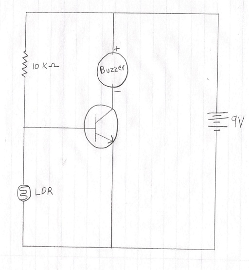
2. Use the circuit diagram and make the connections as follows.
3. Punch in the transistor on the breadboard.
4. Connect the emitter of the transistor with negative side of breadboard using a wire.
5. Connect the LDR with base of transistor and negative side of breadboard.
6.Connect the buzzer with collector of transistor and positive side of breadboard.
7. Now connect the 10k ohm resistor with base of transistor and positive side of bread board.
8. Now connect the battery and at this time the buzzer would be ringing.
9. Now drop the laser light upon the receptive surface of the LDR and the buzzer stops ringing.
Cheap laser pointers that we find in most stores are generally restricted to 5mW or less. These are generally considered safe. However, it is still possible to damage your eyes if you are not careful. When working with lasers, it is a good idea to wear the appropriate eye protection. Avoid looking directly at the laser diode. Also never point lasers at aircraft.
• This circuit is based on LDR(Light Depended Resistor),variable resistor in which the resistance varies according to the light intensity falling on it.
• LDR and resistor R1 forms a potential driver network which is the main
• The voltage drop across the LDR is used t drive the transistor switch. When the voltage drop is above cut in voltage(0.6v),the transistor is turn ON.
• LDR has low resistance in the presence of light and high resistance in the absence of light.
• In our security alarm, a laser light is allowed to fall on the LDR continuously using 3 mirrors.
• Light from another source should not allowed to fall on the LDR, so place the LDR in a box with a single hole to pass laser.
• In this situation the resistance offered by LDR is too low. Since the LASER light is continuously
• In this situation the resistance offered by LDR is too low .Since the LASER light is continuously allowed to fall on the LDR surface.
• Thus the voltage drop across the LDR is also low [V=IR(Ohm’s Law)] which is insufficient to turn ON the transistor, so the transistor remains off state.
• When a person makes a blocks to the continuously flow of LASER beam
• While resistance increases voltage drop also increases when this voltage drop exceeds cut in voltage of silicon NPN transistor(2N7000) it will turn ON.
• Then current from vice starts flowing to ground via the buzzer and transistor, which makes the beep sound.
• The beep sound from the security alarm gives the indication of some security failures.
A laser security alarm is a system designed to detect intrusion – unauthorized entry – into a building or area. They are also called security alarms, security systems, alarm systems, intrusion detection systems, perimeter detection systems, and similar terms.
Burglar alarms are used in residential, commercial, industrial, and military properties for protection against burglary (theft) or property damage, as well as personal protection against intruders. Car alarms likewise protect vehicles and their contents. Prisons also use security systems for control of inmates.
Some alarm systems serve a single purpose of burglary protection; combination systems provide both fire and intrusion protection. Intrusion alarm systems may also be combined with closed-circuit television surveillance systems to automatically record the activities of intruders, and may interface to access control systems for electrically locked doors. Systems range from small, self-contained noisemakers, to complicated, multi-area systems with computer monitoring and control.
Laser security systems are a high tech technology that used to be a part of home security only available to the wealthy. It is manually switch dependent sensors and a basic alarm unit. Laser security system a person moves in front of the sensor, that person triggers the system’s alarm by cutting the laser. And the alarm signals the security monitoring company and local law enforcement. The basic alarm unit will also sound a loud alarm. Both analysis and experiment indicate that rather stringent requirements must be met in order to obtain efficient optical heterodyne detection. At some wavelengths it may provide the only means of overcoming noise and detect noise problems. The operation of LDR depends upon the photoconductivity process.
• www.wikipedia.com
• www.encyclopedia.com
• www.sciencejournals.com
• www.zetascience.com
• www.scribd.com
• www.makezine.com
• www.electroschematics.com
• www.easycircuits.com
• www.youtube.com www.howcast.com
