


Published on Nov 30, 2023
With fuel hikes making news, solar energy is the most sought after energy source. Solar chargers are simple, portable and ready to use devices which can be used by anyone especially in remote areas. Going solar can solve more than one problems, right from cutting down on carbon emissions and dependence on fuels, to solving the energy crisis. This project aims to make a simple solar charger which can be used on the go. Solar panels don’t supply regulated voltage while batteries need so for charging. Hence, an external adjustable voltage regulator is used to have the desired constant voltage. A zener diode switches on to ensure charging is cut off at the saturation point.
Gone are the days when you would look up at the Sun and curse yourself for being out on a hot sunny day. Take pride; very soon you will be a walking energy station with people asking you to help them charge their batteries with your clothes!
This isn’t a scene out of a Sci-Fi movie. It is the simple application of solar cells. They are the only way we can convert sunlight into electricity directly and day by day they are getting better, smaller and cheaper.
Nothing can dare challenge the sun when it comes to radiating energy. Every hour the energy available from the sun is more than what human’s require for an entire year. Petrol, diesel and all these fossil fuels are nothing but sun’s energy concentrated over years and years. This makes them very efficient in terms of energy per unit of the fuel. So why not tap it directly?
Solar energy isn’t something new. People have used sun to dry and preserve things. Vedic literatures in India even state the use of flying machines which were powered using the sun. Come 21st century, we have come a long way in developing solar cells which are the devices powering our future, converting sun’s energy into electricity.
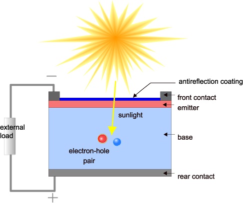
Solar panels are simply solar cells lined up together in series and parallel so as get sufficient voltage and are p-n junction semiconductor devices with pure silicon wafer doped with ‘n’ type phosphorous on the top and ‘p’ type boron on the base. If the PV cell is placed in the sun, photons of light strike the electrons in the p-n junction and energize them, knocking them free of their atoms. These electrons are attracted to the positive charge in the n-type silicon and repelled by the negative charge in the p-type silicon. Connecting wires across the junction will have a current in them.
Solar cells have come a long way from bulky 6% efficient chunks to thin films with as much as 30% efficiency. They are selling like hot cakes today given their necessity and utility. And the reason being they are faithful good chaps unlike oil which will soon be more precious to us than diamonds and the black monster: coal which has polluted the air, hand in cuff with the other fossil fuels.
We need to understand solar panels so as to understand their applications. Today, we have mono-crystalline, polycrystalline and amorphous thin film panels. Mono-crystalline are so far the most efficient, given that they have the maximum silicon in a unit area so more current for the same number of photons. They are made out of a single silicon crystal as a continuous lattice. While for the polycrystalline panels, molten silicon is poured into molds and separate boundaries can be seen due to this. Lesser quantity of silicon in a unit area means lesser efficiency of production of electricity. Amorphous thin film panels are layers of silicon on a glass surface and are the least expensive. Hence, they are used in applications where you can do away with efficiency for lowering the costs.
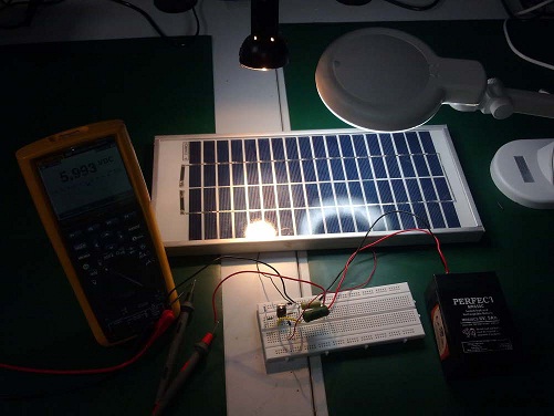
Solar panels are really useful in broad daylight but we need energy when the Sun isn’t shining above our rooftops. That’s why we need solar chargers which will store energy in rechargeable batteries. This project aims to make a solar charger using a voltage regulator IC so as to charge a Lead Acid Battery with the constant output voltage obtained through this IC LM317( Details explained later). Today there are many more options like a SOLAR CHARGER IC LT3652. This is an IC with embedded MPPT (Maximum Power Point Tracking) algorithm. MPPT simply means the IC gets the maximum possible power from the solar panel by sampling its output and applying the proper load resistance. This small chip simplifies life given its ease of use and maximum efficiency is always ensured.
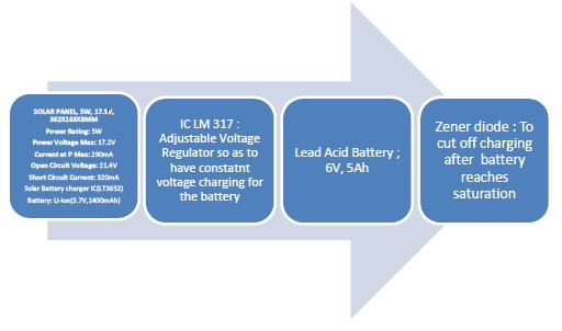
This project aims to make a solar charger circuit using IC LM 317 which is an adjustable voltage regulator.
This solar charger then charges a Lead acid battery which in turn will power our solar lamp.
Note: Several options are available in solar charger circuits but I chose to have IC LM317 given the limitations in availability of the ICs as well as the learning involved in having an entire analog circuit as compared to just having a ready to use Solar charger IC.
Components Involved:
• Solar Panel: The heart of the circuit. It has the following specifications:
i) Voc= 17.4V
ii) Isc= 0.33A
iii) Vmp= 17.4V
iv) Max Power= 5W
This is our power supply. It is responsible for charging the battery.
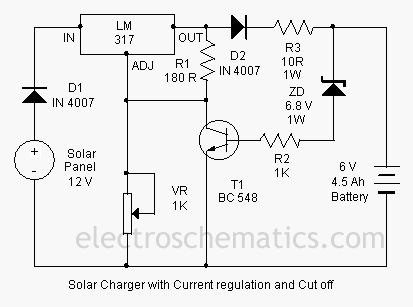
• It is an adjustable voltage regulator IC which means it provides Line Regulation (irrespective of the changes in the input voltage, the output voltage remains constant) and Load Regulation (irrespective of the changes in load the output voltage is fixed).
We can adjust the output voltage by varying the resistance across the adjust pin.
This is needed to have a fixed voltage across the battery (to limit the current and charge it at constant voltage). Directly connecting the solar panel to the battery may even explode it due to the varying output from it.
The voltage across R1 is maintained to be 1.25 V using an internal circuit. The Vout is also then obtained to be constant and given by:
Vout = VR1*(1+R2/R1)+Iadj*R2.
This Iadj is of the order of microA so can be neglected to have a regulated output voltage.
This circuit is designed for a 6V, 5Ah battery. This means a 5A current will charge the battery in 1hour. Lead acid batteries are not the best available options in rechargeable batteries (unlike portable and easy to use Li-ion batteries). But for small applications like our solar lamp, they are good enough. Care must be taken while handling acid batteries.
These are simply blocking diodes which ensure that the current flows only in one way so that the battery doesn’t discharge when the output from solar panel is low.
his part of circuit ensures that once the charging cut off voltage is reached by the battery, the charging stops. The Zener is rated at 6.8V as breakdown. This allows all the voltage to drop across the Zener and the transistor switches on due to biasing of the Base-Emitter junction. The transistor acts like a switch and once the battery is charged, it draws all the current thus protecting the battery.
Note: We conduct experiments step by step to understand how each component works and then assemble the circuit together.
1. TO study how solar panels behave to different intensities of light
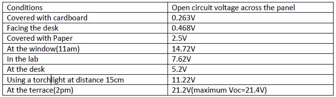
Observations: Solar panels are heavily dependent on the intensity and the nature of light falling on them to produce any kind of voltage. The output varies right from 0.2V to 21.2V.
Conclusions: Sunlight matters a lot. So to make the best out of a fixed solar panel, we need to have some kind of power tracking which will always allow the panel to produce a maximum power by impedance matching (external resistor across the cell).
Conditions: R1=180Ohm, R2=500ohm
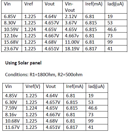
Observations: The output voltage from the IC is observed to be nearly constant with the input-output differential voltage ranging from 2.1V to 20V (Power supply limit).
Results: IC LM 317 gives a regulated output for a particular range of input voltage.
• Solar energy is a clean energy source and it is high time we understand its importance and embrace it in our daily lives.
• Solar cells are the heart of any circuit. In the circuit for this project, Solar panels were used as a power supply and fed into a voltage regulator so as to have a constant voltage charging for the battery.
• Batteries are the easiest way to store energy. Hence solar charger circuits aim at charging batteries rather than driving components.
• Rechargeable batteries like Lead Acid, Li-ion and NiMH are used depending on the user’s requirements. Here we have used sealed Lead Acid ones.
• It is also very necessary to cut off charging once the battery is fully charged. This is managed using a zener diode which switches on at the cut-off voltage and diverts the current through the transistor.
• The battery is thus charged at constant voltage and at desired rate depending on the amount of current supplied.
• Solar energy is the most abundant but least used source of energy. But it’s the solution to most of our problems
• The major challenges we face in going solar is expensive technology, limited space and energy. We need to address them by having more efficient materials and most importantly awareness among people so that they use it to their benefits.
• Solar panels are as good as power supplies of an average of 12V in bright sunlight. The only problem is unregulated voltage due to variation in intensity of light.
• IC LM 317 solves the problem by regulating the output voltage but it again dissipated 2V across it which makes the system less efficient
• Solar charger circuits need voltage regulators so as to charge the batteries at constant voltage.
• The battery charging process should be stopped once it is fully charged and this is ensured using a zener which will start conducting at the cut off voltage.
• The charger circuit is a simple, ready to use lead acid battery charger and is a good way to tap sun’s energy on the go.
• www.main.org/polycosmos/glxywest/vimanas.htm - Indian Flying Machines
• http://www.triplepundit.com/2011/08/solar-farming-potential-india/ - Solar Farming
• http://en.wikipedia.org/wiki/Solar_cell
• http://www.planetarypower.com.au/solar_panels.htm
• http://www.earthtimes.org/energy/solar-cells-future/1403/
• Element14 – to look up devices, ICs
• Physics of Solar Cells- A Text for Undergraduates, J Nelson
