

Published on Nov 30, 2023
In this proposed Research Paper the mobile phone controls a robot by making a call to the mobile phone that would be attached to the robot. During the call activation period, if any button is pressed on the phone in hand, a tone corresponding to the button pressed is heard at the other end of the call that would be placed on the body of the robot. This tone is called dual-tone multiple-frequency (DTMF) tone. The robot perceives this DTMF tone with the help of the phone stacked in the robot. The received code is processed by the microcontroller and then the robot performs actions accordingly.
science and having gained increasing importance in day to day life has thus resulted in more and more scope for study and therefore researchers are taking interest in the robotics which can help people in their daily life. There are three distinct phases that are involved in controlling a robot, via perception, processing and action. Generally, the preceptors are sensors mounted on the robot, processing is done by the on-board microcontroller or processor, and the task (action) is performed using motors or with some other actuators. Generally, wireless-controlled robots use RF circuits. These RF circuits have the drawback of limited working range, limited frequency range and limited control. Use of the mobile phone controlled robot can overcome these limitations, by providing the advantages of robust control. We can make use of mobile phones to control the robots using DTMF technology.
Dual-tone multi frequency (DTMF) is a method used to dial telephone numbers or to issue commands to switching systems. DTMF is widely used for telecommunication signalling between telephone handsets and switching centres over analog telephone lines in voicefrequency bands. DTMF keypads are laid out on a 4x4 matrix, in which each row represents low frequency and each column represents high frequency. With DTMF, each key pressed on a phone generates two tones of specific frequencies. One tone is generated from a high-frequency group of tones, while the other is from a low-frequency DTMF is used in push-button telephones for tone dialling. A DTMF keypad generates a sinusoidal tone which is mixture of the row and column frequencies. The row frequencies are low group frequencies. The column frequencies belong to high group frequencies.
This prevents misinterpretation of the harmonics. Also the frequencies for DTMF are so chosen that none have a harmonic relationship with the others and that mixing the frequencies would not produce sum or product frequencies that could mimic another valid tone. The high-group frequencies (the column tones) are slightly louder than the low-group to compensate for the high-frequency roll off of voice audio systems.
additional functionality of fire detection sensors. In order to control the robot, make a call to the cell phone attached to the robot (through head phone) from any phone, which sends DTMF tunes on pressing the numeric buttons. The cell phone in the robot is kept in “auto answer‟ mode. (If the mobile does not have the auto answering facility, receive the call by „OK‟ key on the rover-connected mobile and then made it in hands-free mode.) So after a ring, the cell phone accepts the call. Press any button on your mobile to perform actions as listed in Table. The DTMF tones thus produced are received by the cell phone in the robot. These tones are fed to the circuit by the headset of the cell phone. The MT8870 decodes the received tone and sends the equivalent binary number to the microcontroller. According to the program in the microcontroller, the robot starts moving.
The tones and assignments in a DTMF system are shown in Table below.
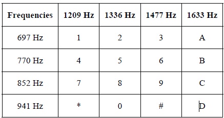
The contemporary keypad is laid out in a 3×4 grid, although the original DTMF keypad had an additional column for four now-defunct menu selector keys. When used to dial a telephone number, pressing a single key will produce a pitch consisting of two simultaneous pure tone sinusoidal frequencies. The row in which the key appears determines the low frequency, and the column determines the high frequency. For example, pressing the '1' key will result in a sound composed of both a 697 and a 1209 hertz (Hz) tone as shown in the table. The original keypads had levers inside, so each button activated two contacts. The multiple tones are the reason for calling the system multi frequency.
These tones are then decoded by the switching centre to determine which key was pressed. The important components of this mobile operated robot are as follows: 1.
DTMF technology is used to decode the tones received by the mobile phone attached to it and pass the command to the motor for movement. Identifies the dial tone from the telephone line and decodes the key pressed on the remote telephone. Here for the detection of DTMF signaling. The DTMF tone is a form of one way communication between the dialer and the telephone exchange. The whole communication consists of the touch tone initiator and the tone decoder or detector. The decoded bits can be interfaced to a computer or microcontroller for further application
Microcontrollers do the important task of reading signals and sensors along with handling the Led displays and the motors. It consists of memory, processor along with input/output peripherals with the ability to provide real time response. Microcontrollers are "embedded" inside some other device so that they can control the features or actions of the product. Another name for a microcontroller, therefore, is "embedded controller”. Microcontrollers are dedicated to one task and run one specific program. The program is stored in ROM (read-only memory) and generally does not change. Microcontrollers are often low-power devices. A desktop computer is almost always plugged into a wall socket and might consume 50 watts of electricity.
Motor driver takes input from the microcontroller and moves the robot in the respective direction provided by the user. It can control two motors simultaneously in either forward or backward direction along with turn if needed.
The sensors used can be used to detect the flame or the heat and respond accordingly. Responses can vary according to the type of sensor and its installation to the entire system. The UV light sensor used in this proposed work can detect the flame faster from a distance as compared to the heat sensor which gets activated after it gets heated to a certain level.
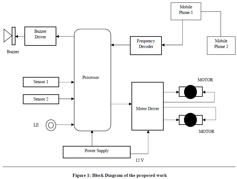
The block diagram given above illustrates the working of the robot in a simplified manner along with the functionality of different sensors to prevent from damage. In the diagram following things are illustrated with the help of figures:
The processor being the heart of the whole system, transfers all the commands to the respective elements attached to it.
If any button is pressed on the mobile phone at the users end, a tone corresponding to the button pressed is heard at the other end of the phone which is stacked at the system.
The robot perceives this DTMF tone according to the button pressed.
The received tone is processed by the processor with the help of DTMF frequency decoder.
The connection between the mobile phone and the decoder is with the help of 3.5 mm jack inserted in the mobile stacked on the system.
The frequency decoder decodes the DTMF tone into its equivalent binary digit and this binary number is sent to the processor.
The processor is preprogrammed to take a decision for any given input and outputs its decision to motor driver connected to it in order to drive the motors for forward or backward motion or a turn which depends on the exact tone perceived by the processor.
There are two motors stacked to the system which work according to the commands given by the user at the other end.
The mobile that makes a call to the mobile phone (Phone 1) stacked in the robot system acts as a remote. So this simple structure does not require the construction of receiver and transmitter units.
The sensors used in the work are used to detect UV light and heat.
As soon as the sensors get activated while the structure is in motion, the command is passed to the processor which in turn activates the buzzer along with turning on the Led and accordingly notifying the user to take necessary actions.
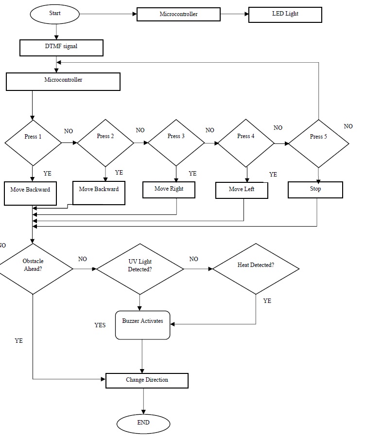
In the proposed research work, following sequence of operations have been followed for position control of stepper motor.
Step 1: The user makes a call to the system mobile phone. The system mobile phone is set in auto-receiving mode. Thus two mobile phones are connected via mobile network and the system mobile phone is now ready to receive the tone from the user mobile phone.
Step 2: The specified key (1 or 2) of the user mobile phone is pressed for selecting the mode of the rotation of stepper motor (i.e. forward or reverse). The keypad tone (DTMF signal) generated due to pressing of keys of the user mobile phone is received by the system mobile phone.
Step 3: The received tone for selection of direction of motion is decoded by the developed DTMF decoder circuit.
Step 4: Microcontroller reads the decoded signal through the I/O port and store the data in its register which in turn decides the digital bit pattern of 1 for forward motion 2 for reverse motion of the stepper motor. Similarly 3 for right turn, 4 for left turn and 5 to stop the Robot.
Step 5: Now similarly any key on the user mobile is pressed for desired position and the corresponding DTMF signal is decoded and then received by the Microcontroller which executes the software program and generates the control signal for motor movement.
Step 6: Control signal generated by the microcontroller is fed to the I/O port and then to the stepper motor driver for driving the stepper motor at the desired position.
One of the best functionality is the addition of IR Sensors. IR sensors can be used to automatically detect & avoid obstacles if the robot goes beyond line of sight. This avoids damage to the vehicle if we are controlling it from a distant place. The proposed system can be modified in order to password protect the robot so that it can be operated only if correct password is entered. Either cell phone should be password protected or necessary modification should be made in the code which handles the robot. This introduces secured access and increases security to a great extent.If the current proposed work is interfaced with a camera (e.g. Webcam) robot can be driven beyond line-of-sight and range becomes practically unlimited as GSM networks have a very large range.
In the proposed system DTMF technology has been used to position the shaft of the stepper motor at a desired point along with different sensors, each performing its own task and all of this in turn may be used in deferent application areas. As conventional RF wireless system has distance limitation, DTMF technology has been used here. The system proposed is very much simple, rugged, and cost effective.
1. Muhammad Ali Mazidi and Janice Gillispie Mazidi, “The 8051 Microcontroller and Embedded Systems”, Pearson Education.
2. L. Schenker, "Pushbutton Calling with a Two- Group Voice- Frequency Code". The Bell System Technical Journal, 39(1), 1960, 235–255, ISSN 0005-8580
3. S. A. Nasar, I. Boldea, “Electric Drives”, (CRC/Taylor and Francis, 2006)
4. V. Subramanyam, “Electric Drives” (Mc-Graw Hill, 1996)
5. Edwin Wise, “Robotics Demystified”, (Mc-Graw Hill, 2005)
