


Published on Nov 30, 2023
This aim of this project is to develop and implement a Quadcopter that is for remotely control via an Android Smartphone. This project involves two main parts, which are (i) control board, (ii) software implementation of PID flight control. A control board has been designed and implemented for driving the Quadcopter. The speeds of four motors are controlled by PWM, which is derived from the command sent from a Smartphone via WiFi or Bluetooth connection. With the use of gyroscope, accelerometer and compass, the flight data are processed to achieve self-balanced flight function. In order to perform flight control, a position PID controller algorithm has also been implemented to for user to control the flight motion.
Quadcopter technology has been researched and potential applications are being study these years. It is a kind of multicopter. Multicopter is aircraft that contains more than two rotors to perform flight control. Motors are often installed fixed-pitch blades. Refer to the word "Quad", it is obvious that the flying machine contains four rotors to perform flight motion. It is a kind of Unmanned Aerial Vehicle. A specific electronic control system with sensors has to be designed for control the flight. The characteristics of small size, lightweight and remarkable mobility make it to be suitable for different missions, for instance, scout of disaster site, aerial transmission line patrol, terrain exploration, and even movie shooting. To explore the technology, a Quadcopter with electronic control system has been developed for Android application to control manually. To achieve the goal, there are several tasks has been completed.
Airframe construction and components selection of power unit
Implementation of Main control board
Implementation of Sensor module
Development of Flight control system
Development of Quadcopter main program
Android application for Quadcopter manual control
Driver development for hardware
Video streaming
Sensor Motion tracking
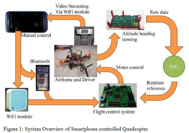
Figure 1 shows the overview of the Smartphone controlled Quadcopter system. To describe the whole project system, a self-develop Android application will transmit manual control command to the digital control system of the copter wirelessly. The Quadcopter can communicate with the Smartphone via Wifi or Bluetooth. After control command received, the main control board that is running flight control system will react for proper copter's motion. The flight control system will refer to the distance between current altitude reference and the target altitude for motor control. To get current altitude reference, open source motion tracking and sensor fusion program, which named IMU, has been used to communication with sensor module for retrieving sensor raw data and process the current altitude heading reference. Moreover, while the Quadcopter is flying, live video is streaming to the phone via WiFi module.
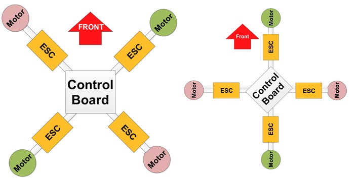
Quadcopter consists of four motors that are installed on the corner of the machine. There are two design approaches of Quadcopter as Figure 2 shown, which are X approach and Plus approach. The difference between them is only the front direction. This will lead to slightly difference on motor control. Motors that are installed on symmetric axis have to be set to same rotation direction. The motors on different symmetric axis are set to rotate in opposite direction. Quadcopter requires installing two kinds of propeller, which are positive propeller and negative propeller. Same type of propellers should be installed to motors on symmetric axis for eliminating torque of rotation.
Motor is a machine that can transfer electronic energy into mechanical energy. The Basic structure is composed of stators and rotors. There are two kinds of DC motors, which are brush motor and brushless motor. The main different between them is that brush motor has brushes to transmitting current into the coil of rotor for providing rotation power, but brushless motor has no brush.
DC brushless motor is always installed onto Quadcopter for flight motion since it has smaller size, lightweight, high rotation speed and high efficiency comparing with brush motor. Normally, brush motor only has 70% efficiency, but brushless one has 78%. The reason is that brushless one has not brush directly connecting to rotor as Figure 3 shown so that there is no heat dissipation and no friction applying on the rotor. DC brushless motor is simply driven by a set of three signals that are shifted 120° phase to each other as Figure 4 shown. By applying the signals to coils, the magnet on the outrunner rotor will be repelled and attracted to perform rotation.
To generate the three phase-shift motor signal, electronic speed controller (ESC) for brushless motor is needed to convert PWM signal into the particular signals. Many brushless motors are controlled by electronic speed controller. ESC can provide regulated 5V supply to control board by Battery Eliminator Circuit (BEC) that is provided by ESC. BEC plays a vital role in power supply of electronic control system. It can provide stable supply to control board when machine is flying.
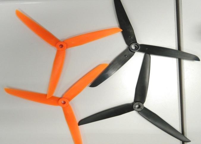
As mentions in "Design of Quadrotor Structure", propeller is important to Quadcopter flight control. Difference propeller will provide difference lift force. Two main concerns on selecting propeller are diameter and the pitch angle of blade. The propeller with larger diameter and pitch angle can produce larger lift force (thrust). The more blades in a propeller, the larger thrust it produces since the contact area between blades and air are increased. For instance, comparing a three-bladed propeller and a two-bladed propeller, which both have the same pitch angle and diameter, three-bladed propeller produces larger thrust.
Quadcopter flight motion is divided in to three components, which are pitch, roll and yaw. By applying different motor speed on each motor, different rotation altitude can be obtained. While Quadcopter is rotating to other angle except remain horizontally, a particular force is acting to air and Quadcopter will begin to move. Taking X approach as example, if the speed of motor 3 and 4 are faster than motor 1 and 2. The Quadcopter will perform pitch motion to move forward. On the contrary, it moves backward. If the speed of motor 1 and 3 are faster than motor 2 and 4. The Quadcopter will perform roll motion to move to right. On the contrary, it moves to left. In case, the speed of motor 1 and 4 are faster than motor 2 and 3. The Quadcopter will perform yaw motion to rotate in counter-clockwise. On the contrary, it rotates in clockwise.
Proportional-Integral-Derivative (PID) control is a widely used control technology. It is a close-loop negative feedback control system as Figure 9 shown. The control algorithm requires current system status information and the desired system status for iterative computation to provide proper reaction to force the system back to stable. By finding out the error (e(t)) between desired and current state at the particular point of time, the error can be input find put the proportional reaction force (KP * error), steady error correcting force (KI * integral of error) and damping force (KD * distance of current error and previous error) can be computed to control the system. The damping force is to reduce the proportional effect that is applied to the system. Proper parameters of KP, KI and KD lead to fast response and stable control system.
An IDE named CoIDE was used in the project for developing firmware of the Quadcopter. CoIDE is a software integrated development environment for embedded system programming. The IDE is mainly designed for ARM Cortex-M series MCUs and providing highly integrated development environment. Using the platform is free of charge. By comparing with other IDEs, such as Keil μVision IDE, CoIDE has no code size limit, more convenient graphical user interface and simple configuration for compilation and flash.
Sketchup is free 3D CAD software that supports 3D printing model design. Sketchup is easy to use with plenty of online open source models that are also free-of-charge. To speed up the development process, design guide is also available in the development environment as Figure XX shown. Since it is free of charge and easy to use, it has been used to design the PCB holders of Quadcopter. All the designed holders are produced by 3D printer
To develop Quadcopter, implementation of electronic control system is necessary. Specific Quadcopter control board is needed for the system. It includes electronic circuit and circuit board layout design. Electronic circuits are always implemented on Printed Circuit Board. Therefore, tool for helping the sophisticated design is needed. Eagle 6.3.0 Professional has been chosen to design the control board. It provides three main functions for design. They are schematic circuit drawing (shown as Figure 13), PCB layout design (shown as Figure 14) and CAM Processor Jobs (shown as Figure 15). CAM Processor Jobs provides aid of generating the specific data of the PCB board for manufacturing.
To debug the control system, data has to be transmitted to computer. In this project, USB-to-TTL adaptor or Bluetooth module are used to transfer data between Quadcopter and computer. To capture the information from Quadcopter and configure the aircraft, Putty is used. Putty is terminal software that can connect different kinds of communication port. It supports server login, proxy, telnet, SSH and serial interface as Figure 16 shown. Additionally, data logging is another key function that it provides as Figure 17 shown. It can be set to record all the data flow through the connection for further use. In this project, Putty has been used to configure the Quadcopter through Bluetooth serial interface for PID tuning.
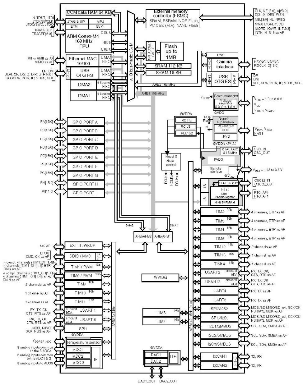
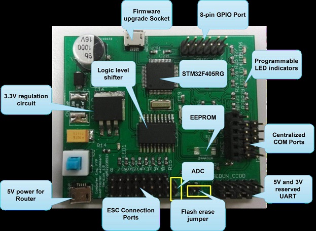
STM32 ARM Cortex-M4 32-bit microcontroller has been used for developing the Quadcopter in this project. The specific microcontroller part number is STM32F405RGT6 as Figure 22 shown. STM32F405RGT6 is the MCU that carries Floating-point Unit (FPU). FPU can speed up the computation when there is floating point in the arithmetic operation, for instance, flight motion tracking. The maximum working frequency of F405 can be up to 168MHz. It provides three 12-bit ADCs, twelve 16bit-timers, two 32-bit timers with PWM feature, six UART and two I2C communication interface. With the rich of peripherals and computation performance, it is suitable for the Quadcopter design in this project.
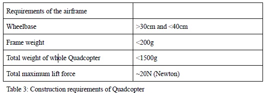
The basic structure of the airframe is divided into frame selection, power unit determination and the electronic control system. Some Hardware requirements except the electronic control system have to be defined before building the Quadcopter. The requirements are represented as follow:
According to the requirements that are stated, compulsory components have been selected with proper justification in the following.
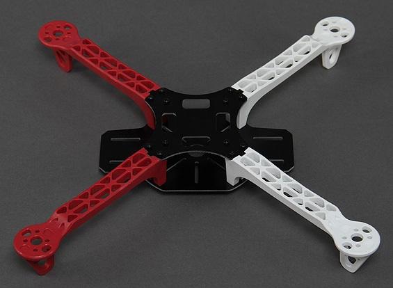
Since the wheelbase of Quadcopter frame has been decided to between 30 and 40cm, a wheelbase 33.0cm frame was chosen. The whole frame is made by Nylon and fiber. There is a power distribution board, which is designed for powering the electronic speed controller, integrated into the frame. There are many airframes, which are made by carbon fiber, in the market. When considering the material of airframe, weight should be the first choice. However, the main concern of the construction of Quadcopter is that Quadcopter with smaller size could be easier for developing and testing. Therefore, a smaller frame has been chosen. The weight of the frame is about 157.0 g.
A2212 1400KV Brushless motor and 7-inch three-bladed 7035 propeller has been chosen for the components of the power unit. The number of 1400KV is defined for specifying the rotation speed of motor will increase 1400 rounds per minute by 1-volt supply increase. In addition, the value 7035 of the propeller means that it has diameter of 7.0 inches with 35 degrees pitch in each blade. Different pitch angle can provide different thrust. Due to the size of the chosen frame, propeller with longer diameter than 7 inches cannot be installed. However, considering to the lift force that the whole frame may demand, three-bladed propeller with 7-inch diameter has been chosen. Due to the flight control feature of Quadcopter, it requires exactly two positive and negative propellers, noted as P-propeller and N-propeller, for eliminating the torque of rotation. The same type of propeller will be installed on the symmetric axis respectively.
A2212 1400KV Brushless motor has been chosen. According to the RPM=KV×Volt, the maximum rotation speed (RPM) of the motor (KV = 1400) can be up to 16800 round per minute under a 3-cell Lithium polymer battery supply (Volt = 11.1). 16A current is required to perform maximum rpm for the chosen brushless motor.
Since 7-inch three-bladed propeller is used, the thrust is near to thrust of 8060 propeller, which is two-bladed with diameter of 8 inches. It should be enough to lift up a 1.5 kg Quadcopter by grouping four sets together. The total weight of four sets of brushless motor with propeller is about 200 g.
PWM driven 40A Electronic speed controller (ESC) has been chosen for driving the A2212 1400KV brushless motor. Each motor will be allocated one ESC for speed control. The continuous current output meets a 1400KV motor required. By considering the power rating of the selected brushless motor, Skywalker 40A ESC has been chosen. The supply for this ESC and the motor are the same, which is 2 to 3-cell Lithium Battery. The electronic speed controller is pulse width modulation (PWM) signal driven. Motor speed (throttle) can be controlled by different duty cycle of the PWM signal. However, there is a range of duty cycle for driving the throttle via the ESC. Zero to full throttle range is mapped between 5% to 10% duty cycles. The total weight of 4 ESCs is about 172 g (43 g for each).
A 3-cell Lithium polymer battery with 2700mAH 25C has been chosen, which can provide maximum 65A continuous current. According to the maximum current requirement of the Power unit, 64A continuous current is requirement. Since the Quadcopter is designed not to fly in maximum power, current draw will seldom exceed 60A. The chosen battery should be enough to the demand.
Base on the components, which are selected previously, the total weight of the airframe with power unit is round 720 g. By adding the weight of all the electronic components that are required in this joint project, the estimated weight may increase to 1.2 kg at most which is far less than the construction criteria. Those electronic components are sensor module, main control board, Wifi module and camera.
MCU is the main concern of the control board design. By reaching many designs of the open source Multicopters, it has been found that Arduino ATmega328p is widely used for developing those kinds of aircrafts. However, STM32F405RGT6, which is ARM Cortex-M4 architecture, has been thought to be a possible option. Therefore, microcontroller has to be decided by comparing both two kinds of MCUs. After the following comparing, STM32F405RGT6 MCU has been selected as the brain of Quadcopter finally with reasons. Selection of Microcontroller The Microcontrollers' comparison table is shown as follow:
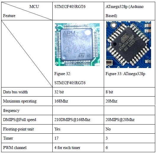
Numbers of PWM channels in both of the microcontrollers are sufficient for controlling four brushless motors. However, STM32F405RGT6 contains floating-point unit (FPU) for performing floating-point calculation. Accurate Motion tracking requires floating-point value computation and large data bus width. If the operation is done by MCU without FPU, like Arduino ATmega series, the speed of each iterative motion tracking will be slow down. In addition, STM32 MCU provides much larger bit width for computation, which contributes to result that is more accurate. Unstable flight control may be caused by the slow motion tracking which will contribute to integral error while flying. Therefore, a high computation performance MCU with FPU is required.
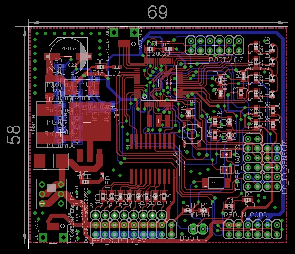
The first version of main control board is suit to the whole Quadcopter system design, and has no design fault. The size of main control board is 6.9cm * 5.8cm as Figure 74 shown. When PCB has been designed, larger trace width has been chosen for power supply, including 5V and 3.3V. Moreover, ground plane has been added to the layout after all the wires are traced.
After the design of PCB layout, gerber files are output from the Eagle 6.3.0 for PCB manufacturing. Nine files are required to send to the PCB factory. Their file extensions are ".cmp", ".drd", ".dri", ".drl", ".gpi", ".plc", ".sol", ".stc" and ".sts". Before sending them to the factory, 3D PCB preview has been done to confirm the PCB design and output file are identical. "Online 3D Gerber Viewer" has been used for preview.
After manufacturing, PCB of the control board has been received. Then, components have to be soldered to the board. The most difficult part is to solder STM32F405RGT6 Microcontroller onto the board. Since the package of STM32F405RGT6 is LQFP64 (10mm x 10mm) which contains 64 pins with 0.2mm adjacent space. To solder this kind of surface mount IC, special technique is needed. Soldering paste, heat gun and soldering braid has been used to mount the IC. First, soldering paste has been thinly coated to the SMD pad on the same edge as Figure 78 shown. Then, PI Silicone tape has been used for fixing the IC on to exact position. After that, heat gun, which has been preheated to 250℃, has been placed on top of the thin coat until all of the paste is mounting to the pins. Then, soldering paste has been coated to the rest of three sides and soldered by heat gun. Finally yet importantly, redundant solder has been absorbed by using soldering braid.
According to PID control theory, it is a close loop feedback control. To form a close loop, sensors for sensing status of system are needed. Control system requires information that represents current system status to compute and determine proper reaction to stabilize to desired state. PID algorithm has been implemented in the flight control system. To obtain current flying altitude heading, three kinds of sensors have been used to provide information as reference. A sensor module has been implemented by another group mate in Part (II) of this joint project. The sensor module is shown in Figure 83. MPU6050, which combines 3-axis accelerometer and 3-axis gyroscope and HMC5883L, which is electronic compass, have been implemented onto the module to provide totally 9-axis motion tracking dimensions. To clarify, since on the current development purpose the rest of components on the module are not necessary to the design of flight control system. Therefore, most of them have not been soldered on to the board yet.
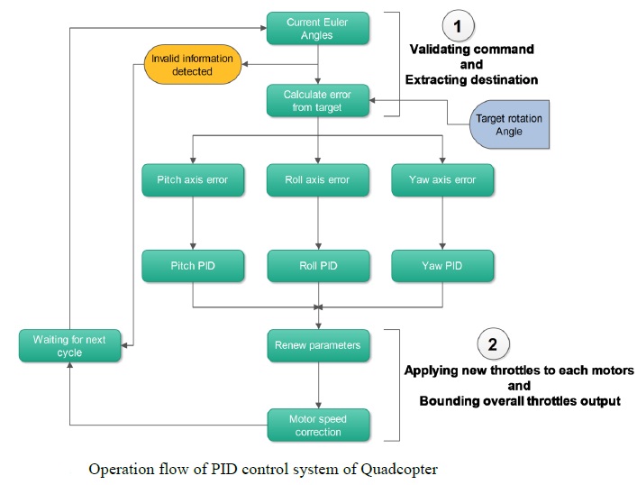
Since raw data from the three sensor ICs are not stable and even have drifting property, sensor fusion has been completed to perform motion tracking by Part (II) of this joint project. Therefore, the part of flight control is responsible to compute according to the android control command and current altitude heading and perform proper reaction. To perform fight control, the system has to extra the target 3D rotation angle from the manual control command and retrieve current 3D rotation altitude from the motion tracking result. Then, target angles and current angles have to be separated into three dimensions, which are pitch, roll and yaw. Error, which is so-call distance, between each group of target and current angles will be calculated for input into three separated PID controllers. Therefore, proper throttles to each motor along with three different rotation axes can be calculated. Then, throttles for the same motor are added together and passed to motor driver with maximum throttle boundary for motor speed control. Before finishing current iteration, errors along the pitch, roll and yaw axes of that cycle has to be backed up for next PID cycle. By continuously running the PID controller, the motion of Quadcopter will be stabilized, and flight motion can be correctly performed with a set of suitable P-I-D parameters.
Since user may only manually control the Quadcopter without using height lock and GPS auto-flying, it may not be necessary for the Quadcopter to bear other sensors that are not used at all. Weight is a critical issue for aircraft. Sensor module could be reduced to only the two ICs, which are MPU6050 and HMC5883L. A smaller sensor module can be designed for the purpose. Moreover, passing the task of motion tracking to the module could share the computation complexity so that STM32F405RGT6 could be replaced by a microcontroller with lower computation performance. This could also reduce the cost of Quadcopter. To illustrate, price of STM32F405RGT6 is around 50 HKD. However, replacing the F405RG by two STM32F103T8 MCU could be reduced 20 HKD. New MCU could still provide necessary computation performance, PWM channels and communication port, such as I2C and UART, for flight control. The purpose of adding a microcontroller to sensor module is that the MCU can perform motion tracking by processing the information of sensors and only pass the current altitude heading reference information to control board. Therefore, the sensor fusion and data filtering are transparent to control board.
[1] RC UNIVERSE, Brushless Basics Available: http://www.rcuniverse.com/magazine/article_display.cfm?article_id=1344 BrushMotors7.jpg
[2] Orientalmotor, Speed Control Methods of Various Types of Speed Control Motors Available: http://www.orientalmotor.com/technology/articles/article166-1e.html No166-fig14.jpg
[3] Notes for the lecture on sensors and sensing (02/11/02), Sensor and sensing Available: http://cs.brown.edu/~tld/courses/cs148/02/sensors.html pid.gif
[4] STM32F40X Datasheet Available: http://www.st.com/st-web-ui/static/active/en/resource/technical/document/datasheet/DM00037051.pdf
