


Published on Nov 30, 2023
Segway was once a mysterious invention created by Dean Kamen. The Segway Human Transporter is a personal transport device that uses a built-in computer to remain upright. The aim of this project is to mimic the design of the Segway and build a low cost DIY Segway. The first stage of this project is to design the mechanical structure of the transport device. According to different power and functional requirements, different mechanical and electronic components have been chosen for the implementation. The rider shifting weight and a manual turning mechanism on the handlebar are used to control the speed and direction of the Segway. Gyroscope and variable resistor are used to monitor user’s physical motion. The control board used in this project is an Arduino ATMEGA2560. A control software for monitoring the sensor readings, calculating PID and also outputting motor speed values has been developed. The two motors are controlled by a Maxon power board which receive signal from a purposely built DAC board. The control board varies the Segway speed by sending required data to the DAC board.
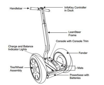
Dean Kamen first introduce the idea of personal transportation during the mid-1990. Nowadays, this invention – Segway Human Transporter, is common sight around the world. The Segway PT is a two-wheeled, battery-powered, self-balancing electric vehicle . The two coaxial wheels driven independently by a controller that balances the vehicle both without and with a rider. Sensors and gyroscopes in the car base give the feedback for regulation of balancing. The system is responsive to provide adequate balancing for different riders and riding styles and it is robust enough to accept riders of different weights A user can command the Segway to go forward or backward by shifting their weight on the platform. The Segway will detect the tilting angle and the change in its center of mass. In order to maintain balance, it will first establishes and then maintain a corresponding speed to go forward or backward. A handle bar is used for user to command the car to go to left or right. The Segway can reach a maximum speed of 12.5 miles per hour.
The Segway PT that sold on website consist of the above components and subsystems. The follow shows some steps in using the Segway PT. This project is going to mimic some of the steps, functions and components to design the DIT Segway.
1. Choose a flat and smooth area to start up your Segway. User should put on their helmet when riding this car.
2. The handlebars on the Segway should be adjust for a comfortable and safe ride.
3. User should find the mode button, key port, display and steering grip on the handlebars. The display will provide information for a safe ride.
4. Segway need to be turn on by putting the key into the key port. User should stand on the side of the Segway and tap and hold the mode button. A green smiling face on the display represent the Segway is ready to ride.
5. The balance mode should be tested by moving the handlebar back and forth to see if the wheels respond.
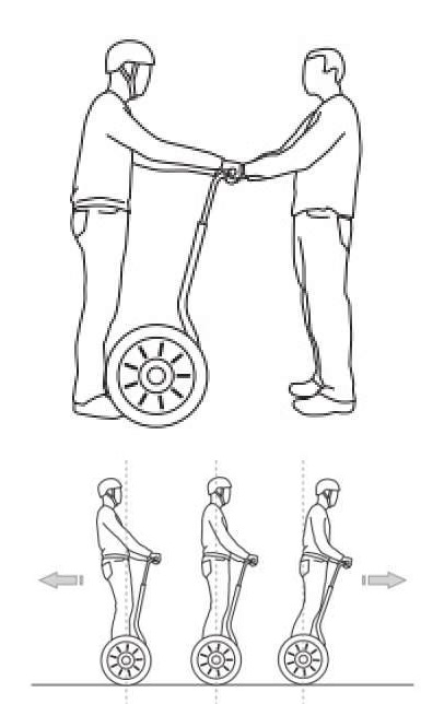
6. When a rider is ready to step on the Segway, another person should stand in front of the Segway and hold the handlebar securely. After the rider step onto the Segway, the rider should stand straight and feel the Segway balance.
7. Rider should keep their legs and arms loose with knees slightly bent. Rider should grip the handlebar lightly
8. Rider could lean forward to more the Segway forward and lean backward to travel backwards on the Segway. To turn the car, rider can shift the handlebar.
9. When rider want to stop he should first shift his weight to the centre. Rider should step off the Segway one foot at a time. After stepping off the Segway, the power should be turned off.
When Segway was first invented, it develop a reputation for being nerdy and useless, but in the last few years people found plenty of things that it can be used for. This personal transporter become more popular as more uses are found and the gas prices rise.
Segway Polo is like regular polo, players ride on a Segway instead of houses. Segway PT is used on the field. Two teams of five players each hit a ball with their mallets and try to get the ball into other team’s goal. The first organized match was in 2004 and now the game is played worldwide.
Many historical areas and cities offer Segway guided tours. Sightseeing can be hard and tiring on the feet. This easy mode of transportation allows visitors to quickly glide around town from point to point.
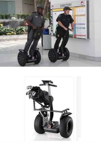
The maximum speed of the police use Segway can reach to 12mph. Although it could not keep up with a car, police can kept the road in sight. It was easy to catch up with the perpetrators when they were on foot. The Segway widens their field of vision which help them arrive an emergency scene more safely and quickly.
Segway have different models that suit for different usage. There is off-road models for some off road sports. There are also “Segway X2 Golf” which is a special model that equipped with special tires and golf club bag for golf players to use.
Gear motor is a design that allows low horsepower motor to drive a large force on an object but with a low speed. The increase in torque is inversely proportional to the decrease in speed. With the gear motor, even a small motor can support as large torque as human weight. To choose a motor, the following calculations need to be carried out:
1) Convert mph to km/h
2) Convert km/h to m/s
3) Calculate the force
4) Calculate the power of the motor
5) Calculate the rpm and the diameter of the wheels.
Segways found in market have three different speed standard to suit for different level of users. For the beginner standard, the maximum speed is 6mph. For intermediate standard, the maximum speed is 8mph. For the advance standard, the maximum speed is 12mph. In addition, the standard Segway weighted 60kg.
The battery chosen in this project should have at least 24V and 17A to support the motors and the system to operate. The lead–acid battery is the oldest type of rechargeable battery. It is able to supply high surge currents and the cells have a relatively large power-to-weight ratio. The price of these kind of battery is relative low and it is popular among motor vehicles for the high current requirement.
Each battery can have a voltage level of 12V, by connecting two battery in serious can achieve the target of 24V. This set of batteries was used in the early stage of the project. Considering the weight of them, another replacement was researched.
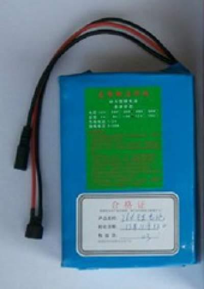
Lithium Iron Phosphate battery is the battery that used in the finalized Segway. The voltage and current level of it is 24V and 20A. It is enough for supporting the system to run. Lithium Iron Phosphate battery can provide stable voltage output upon fully charged. The chemical is non-toxic, green and stable. It can be worked under high temperature and the lifetime is long. Weight of this battery is about 4.5kg which is suitable for small vehicles.
Maxon Motor controller is a powerful servo amplifier, it can be used to drive motors from 80Watts up to 500Watts. It support different mode depends on user requirement. User can choose to use a tacho signals or an encoder signals to control the speed. There is also torque or current control and IxR compensated speed control. Maxon Motor controller is protected against excess temperature, short circuit and excess current on the motor winding. The efficiency of the motor control can reach to 95% with the FET power transistors incorporated in the servo amplifier. It support a nominal supply voltage range of 12-50VDC. The maximum output current can reach 20A. It is suitable for using in an electric vehicle with require high power.
Atmega2560 is the controller that use on Arduino Mega2560 microcontroller board. It has 15 PWM output, 16 analog inputs and 54 input and output pins. The board provide a USB connection, a power jack, a reset button, and ICSP header and a 16MHz crystal oscillator. To program the device, user can connect the board to the computer using a USB cable. Accept from USB port to supply power, the board can be also power up by connecting the power jack with a 5V supply.
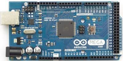
Many computer have an internal protection on the USB ports. This Arduino board provide an extra protection of a resettable polyfuse that protect from overcurrent or short circuit. If there is more than 500 mA applied to port, connection will be automatically break until overload or short circuit is removed. It is useful during debugging stage as the Segway system under test is running at a high power level which may damage the computer if accidents occur.
MPU-6050 combines an on board Digital Motion Processor with a 3-axis accelerometer and a 3-axis gyroscope on the same silicon die. It can be used to process complex 9-axis Motion Fusion algorithms. Communication with MPU-6050 is achieved over two pins SCL and SDA. He AD0 pin can be connected to ground of VCC, it determine the I2C address of the chip. This AD0 feature allows you to have multiple gyroscopes without mixing the I2C address together.
A variable resistor is a three-terminal resistor with a continuously adjustable knob in which use can rotate it to adjust the resistance value. These resistors are known as the potentiometers, they act as a continuously adjustable voltage divider. One of the example usage is the volume adjust in a radio. When a user turn the knob the pointer will rotate to a corresponding location. The resistance value is depends on the length of the yellow circle it touch. With the above equation, the analog output of the resistor will be vary according to the resistance value.
Digital to analog converter is the circuit that performs the digital to analog conversion. This process is to convert signals having a few defined levels or states into signals that have a theoretically infinite number of states.
I2C is a communication protocol uses 2 signal lines. They are called SDA (serial data) and SCL (serial clock). It is a multi-master protocol in which the number of slaves and masters are not limited. Each slave will have their own unique address. When a master want to address the slave, the address is used in waking up the slave device. First, master will issue a start signal. All the device on the bus will listen to the incoming data. Then master will sends the address of the device it is going to access and also whether it is going to read or write. After that all the device will compare the address, device that are not match will wait until the bus is released by stop signal, the device that match will produce a acknowledge signal. After the acknowledgment, master can start to transmit or receive data and slave will start sending the requested data byte by byte.
SPI is a single-master communication protocol. A central device is named master and it is responsible to initiates all the communications with the slaves. When a master want to send data to a slave or request data from slave, it need to select the slave by pulling the SS line low and activates the clock signal with a clock frequency that is usable by the master and the slave. The master will then generates information onto the MOSI line while it will samples the MISO line to receive data
Arduino is an open source computing platform for Arduino microcontroller board. It provide a development environment for user to write software program and upload to the controller. The extensible software and the open source resources provide user a clear and simple programing environment. Arduino board is cheaper comparing with other microcontroller which is suitable for project development.
Kalman filter is known as the linear quadratic estimation. It is an algorithm that use a series of measurements observed over time to produces estimations. These data contains random variations like inaccuracies and noise. Based on the data, Kalman filter can produce the value of an unknown variable that tend to be more precise than measurement done alone. Numerous applications in technology can apply Kalman filter. A common application is for navigation, control and guidance of aircraft, spacecraft and vehicles. It can also be applied in time series analysis used in fields such as econometrics and signal processing. The Kalman filter algorithm works in a recursive manner. In the prediction step, Kalman filter produces estimation of the current state variables along with the uncertainties. When the next measurement is read, together with the random noise and error, the estimation model is undated using a weighted average. After a few run, with more weight being given to estimates with higher certainty.
P, I, D stands for proportional, integral and derivative. A PID controller is a control loop feedback mechanism used in some industrial control system for example temperature control. PID control calculates and error value as the difference between the desired set point and a measured process variable. The controller attempts to minimize the error by adjusting the process control inputs. The three value P, I, D is constant parameters that used in the control algorithm. Proportional depends on the present error, integral is the accumulation of the past errors and derivative is a prediction to the future error based on the current rate of change. P, I and D can do different combination depends on the system needs. It can be changed into a PD, PI, I or P controller.
Eagle is a PCB design software, it stands for Easily Applicable Graphical Layout Editor. Eagle is a powerful, user friendly and affordable for users to implement their PCB design. It included variety of functions for example library drawing for electronic components, schematic drawing and board layout design. Eagle is a popular PCB design software that consist of lots of online or build in libraries to support user’s design. The build in standard libraries consist of some normal use components. If user cannot find the required components in the build in library, a lot of libraries can be found on web or even users can design their own components. After the design, user need to fabricate the PCB. Eagle software provide a Gerber file output for user’s PCB layout. User can choose the required file or data from the setting and these files can be used in fabrication.
The Segway is a product that can be used in many different kind of area. It can be used in some parks like Ocean Park or Disney land for visitors to navigate. It can also use to replace police car for policemen to make an arrest. There is no lack of examples for the using of this product. Many of the tourist sight in Singapore have Segway Eco Adventures. User can ride on a Segway and pay visit to the beach sides and some off road areas. In China, Segway was used in some airports and Tiananmen Square for police to patrol. It help to reduce the time for patrols and complete more patrols of the premises in the expected time. The problem of this product is the prize is quite high and also user concern about its’ safety problems. The advertisement is also not enough, as a result it is not very popular among citizens. In Hong Kong, it is not popular and even people have no idea what is a Segway. This project aims to promote the benefits and the use of Segway. As a result, a DIY Segway was build up with some necessary components and mechanisms, so as to demonstrate the ideas of this personal transporter.
1. Arduino ATMEGA2560
2. 24V Lithium Iron Phosphate battery
3. DC geared motor x2
4. Maxon motor controller x2
5. DAC board
6. Power board
7. Accelerometer (analog signal)
8. Gyroscope (analog signal)
9. Variable resistor (analog signal)
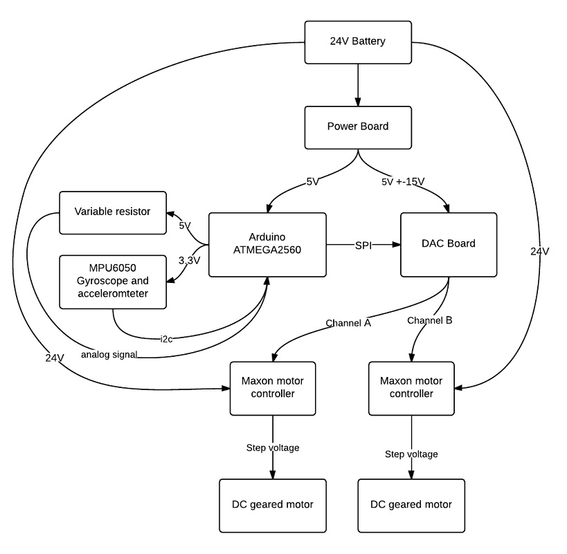
Gyroscope is used to monitor the angle of the car chassis. The gyroscope output gives the angle but it drifts a lot. By combining the result with the accelerometer values and pass though the Kalman filter, the output angle will be more precise. If the car is leaning, micro-controller will notice the angle changed and output a speed signal to the dac board after calculation. The speed of the wheels depends on the leaning angle. Platform balancing is done by controlling the motor speed and direction, and PID is the algorithm in calculating the speed value. The speed value include the direction and magnitude. Variable resistor is used for detecting the turning motion of the handle bar. The value of variable resistor will be originally set to middle. Micro-controller will keep monitoring the analog value of the resistor. If the resistance increased or decreased, which means the handlebar is turned. Micro-controller will give out a signal to speed up one wheel which gives a result of turning left or right.
Over speed problem will be solved depending on the actual model and user, as weight, centre of gravity will also need to be considered. One of the solution to this problem is before the speed of the wheel cannot balance the user as the rider lean too down, micro-controller will increase the wheel even more to push back the rider.
In the first stage of the project two LED is used to simulate the two wheels for testing of the program. The brightness value original is at 60, the minimum value is 0 and the maximum value is 255. The brightness of the light bulb will represent the speed of the wheel, decrease in brightness implies moving backward and increase in the brightness represent moving forward
The system is at stable state when 180 degree. By applying the Kalman filter, the angle output is very stable and keep away from drifting. In this example, the center position of the resistor is set to be 939. The two LED have the same brightness level of 60 in the figure.
A motion of turning the handle bar to the right is simulate by rotate the resistor clockwise. The resistance is increased and the lightness of the right LED is lower than the left one. It simulate the increase speed of left wheel and decrease speed on the right wheel, which will result in turning right
A motion of turning the handle bar to the left is simulate by rotate the resistor anti-clockwise. The resistance is decreased and the lightness of the left LED is lower than the right one. It simulate the decrease speed of left wheel and increase speed on the right wheel, which will result in turning left
The change in tilting angle of car chassis is simulate by adjusting the tilting angle of the breadboard. The increase in the angle value simulate a user leaning forward, which will results in the Segway moving forward. Both LEDs brightness level will be increased.
In the opposite, decrease in the angle value simulate the user leaning backward. It will result in the Segway moving backward to balance the user and both LEDs brightness is decreased.
The steps of using the DIY Segway is shown below:
1. Choose a flat and smooth area to start up your Segway. User should put on their helmet when riding this car.
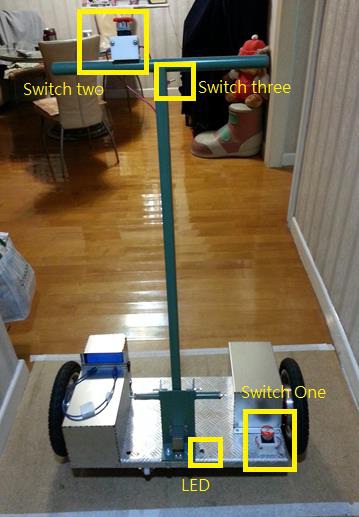
2. Rider should first turn on the switch one for the power up of the system. User should wait until the LED lights up which indicate the success on initialization.
3. Rider should turn Switch three to car self-balance mode. After turning switch three, Switch two can be turn on for powering up of the motors.
4. The Segway is balanced and rider should test the Segway by moving the handlebars back and forth to see if the wheels respond.
5. Rider should step onto Segway with one foot and turn to user balance mode and step another foot onto the Segway.
6. Rider could lean forward to more the Segway forward and lean backward to travel backwards on the Segway. To turn the car, rider can shift the handlebar.
7. To step off the Segway, rider should first shift his weight to the centre to stop.
Next, rider should step one foot off the Segway and turn switch three to car-self balance mode. Finally, rider can step off the car and close switch one and switch two consecutively.
The aim of this project was to design and build a rideable, self-balancing and coaxial scooter, which it is called “The Segway”. This aim has been achieved and a Segway with control and on-board power has been made and successfully tested. A comprehensive literature review was conducted, including software and technical information relevant to the project. Mathematical models and algorithms like Kalman filter and PID control is used to compute the calculation. In one way, it can make the result more precise so as to achieve a better balancing. It can also increase the safety, to prevent the errors in calculations which will affect the speed of motors. A formulated design approach was used to create the most efficient and robust configuration to satisfy all the project goals. The structural design was considered concurrently with component selection, aesthetics, and ergonomics to minimise mechanical, electrical and rider integration problems. The use of safety wheels and control switch provide a high safety and ease of control to the Segway. The outcome of this project has been a mechanically sound, aesthetically pleasing and easy to ride self-balancing Segway.
[1] The Telegraph - What is a Segway? http://www.telegraph.co.uk/motoring/news/8028753/What-is-a-Segway.html
[2] Reference Manuel of Segway PT http://www.segway.com/downloads/pdfs/ReferenceManual.pdf
[3] Wikipedia – Segway polo http://en.wikipedia.org/wiki/Segway_polo
[4] City Segway Tours http://citysegwaytours.com/
[5] Case study- Enhancing the Efficiency at the Airport Border Control http://www.segway.com/downloads/pdfs/BCIAairportcasestudy.pdf
