


Updated on May 29, 2026
In order to make the process of construction easy and to have efficient working and maintenance, the sewer system requires various additional other structures. These are called as sewer appurtenances.
Sewer system requires various types of appurtenances for their proper functioning and maintenance, because simply sewers are laid, the sewage cannot flow in it continuously for longer time .After some time it will be chocked up and requires cleaning of sewers. If sewerage system is not properly maintained silt, ashes, grit, oil, fats, etc. will chock the sewer lines. Therefore, for proper operation and maintenance of sewerage system various devices are required.
These are the appurtenances are as follows.
• Manhole.
• Catch basin.
• Cleanouts.
• Oil & grease trap.
• Inlets.
• Lampholes.
• Drop manholes.
• Flushing tanks.
• Inverted siphons.
• Sewer ventilators.
A lamphole is an opening or hole constructed in a sewer for the purpose of lowering a lamp inside.
The lamphole consist of vertical stoneware or concrete pipes which are connected to the sewer line through a tee junction. The pipes are surrounded by concrete make them stable. At the ground level, the manhole cover with frame is provided to take up the load of traffic.
• Under some circumtences, the lampholes may be also used as flushing device.
• If the cover at the top of lamphole is perforated, the ventilation of sewers is achieved. such lamp hole is known as fresh air inlet.
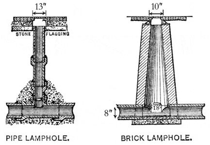
• In narrow lanes change of gradient and slight curves where space is insufficient for the construction of manholes.
• If the construction of manhole is difficult, a lamphole may be constructed in its place.
• When the sewer length is straight for a considerable distance beyond the usual spacing between manholes, the provision of a lamphole is advisable.
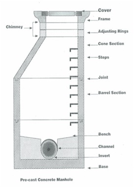
A manhole is an opening constructed on the alignment of sewer for facilating a person access to the sewer for the purpose of inspection, testing, cleaning & removal of obstruction from the sewer line.
The following are the objects of the construction of manholes-
• They permit inspection, cleaning, maintenance of sewer line. The obstructions in the sewage flow are collected in manholes and then they brought to the surface.
• The manholes allow the joining the sewers or changing the direction or alignment or both.
• A manhole sometimes receives the contribution of sewage from sewers of various sizes and coming from various directions.
• If manholes covers are perforated, the manholes may allow the escape of undesirable gases and thus, ventilation of sewers can be achieved.
• The manholes facillate the laying of sewers lines in convenient lengths.
Manholes should be built at every change of alignment, gradient and diameter. At the head of all sewers and branches and at every junction of two or more sewers. On sewers which are to be cleaned manually which cannot be entered for cleaning or inspection, the maximum distance between the two manholes should be 30 mt.
Square manhole cover Rectangular manhole cover
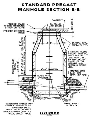
The manholes are constructed directly over the centre line of the sewer. They are circular & rectangular in shape. Manholes should be of such size as will allow necessary cleaning & inspection of manholes.
A) Rectangular manholes-
These are the manholes of sizes like
1) For the depth of manholes less than 0.90mtr, 900x800mm.
2) For the depth of manholes 0.90 up to 2.5 mtr, 1200x900mm.
For the depth of 2.5 & above arch type of manhole can be provided and the internal sizes of chambers between brick faces shall be 1400x900mm.the width of manhole chamber on bends and junction of pipes with dia. greater than 450mm, should be suitably increased to 900mm or more so that benching width on either side of channel is at least 200mm.
The circular manholes may be constructed as a alternative to rectangular as well as arch type manholes. These are the manholes are provided for all the depth starting from 0.90 m. circular manholes are straight down in lower portion and slanting in top portion so as to narrow down the top opening equal to dia. of manhole cover. Depending upon the depth of manhole the diameter of manhole changes. The internal diameter of circular manholes may be kept as following depths.
• For depth above 0.90m and up to 1.65m, 900mm diameter.
• For depth above 1.65m and up to 2.30m, 1200mm diameter.
• For depth above 2.30m and up to 9.0m, 1500mm diameter.
• For depth above 9m and up to 14m, 1800mm diameter.
If the sewers are constructed in tunnel the manhole should be located at the access of working shafts and the manhole chamber must be constructed of a size to suit the working shaft or vice-versa.
The openings for entry into the manhole (without cover) should be of such minimum dimensions as to allow workman with a cleaning equipments to access into the manhole without any difficulty. A circular opening is generally preferred. A minimum clear opening of 60cm is recommended. Suitable steps usually of cast iron shall be provided at entry.
Access shaft shall be circular in shape and shall have a minimum internal dia. of 750mm. Where the depth of shaft exceeds 3m suitable dimensions shall be provided to facilitate cleaning and maintenance.
Access shaft where built of brickwork should be controlled on three sides it to the size of the opening in the cover frame, and to provide easy access on the forth side to step irons or ladder in determining sizes, the dimension of maintenance equipment likely to be used in the sewers shall be kept in view.
Where the dia. of sewer is increased, the crown of the entering and leaving pipes shall be fixed at the same level and necessary slope is given in the invert of the manhole chamber.
A slab, generally of plain cement concrete at least 150mm thick should be provided at the base to support the walls of the manholes and to prevent the entry of ground water. The thickness of the base also shall be suitably increased upto 300mm for manholes on large dia. with reinforcement. in case of large manholes ,the flow in the sewer should be carried in U shaped smooth channel constructed integrally with the concrete base of manhole. The side of the channel should be equal to the dia. of largest sewer pipe.
The side walls of the manhole are usually constructed of cement brick work 250mm thick and corbelled suitably to accommodate the frame of the manhole cover.
The element of the sewer maintenance ignored very often and which requires careful attention and protective measures is the manhole work. The staff should be trained for comparatively easy act of removing a manhole cover, not only to avoid smeshed toes and fingers, but also to prevent more serious back injuries. In addition, the approaching drivers on the road should be warned from a distance about the manhole work in progress by the installation of suitable signals or lights.
The most serious hazard of manhole work are however flammable gas and oxygen deficiency. The staff should be thoroughly trained to carry out simple tests on every manhole before entry for oxygen deficiency, combustible, carbon monoxide or hydrogen sulphide.
If however an emergency demands to enter a gas-filled manhole or one where oxygen may be lacking, the worker should wear a self contained air breathing mask and a safety harness with lifetime. The extra two other employees should be stationed at the manhole opening because one individual cannot life an unconscious person out of a manhole.
• Use safety harness & life line before entering into the sewer line. The two persons should stand at the top and they should give the signals to the person in manholes.
• Test for the hazardous gases before entering into the manhole.
• The manhole should be opened before one hour of the work. The care should be taken that it should be fenced to prevent any person, children in to the manholes. The dummy covers should be provided.
• Use the mask when man have to into the sewer line.
• No material should be kept near to the manhole as it can fall into the manhole which cause the accident.
• Test the ladders of manhole before entering into the manholes.
• The lighting material should be fire proof.
• Lower all the tools into the manhole through buckets only.
When a sewer connects with another sewer, where the difference in level between water lines of main line and the invert level of branch line is more than 600mm or a drop of more than 600mm is required to be given in the same sewer line and it is uneconomical and impracticable to arrange the connection with in 600mm, a drop connection shall be provided for which a manhole may be built incorporating a vertical or near vertical drop pipe from the higher sewer to lower sewer. This pipe may be outside the shaft and encased in concrete or supported on brackets inside the shafts. which should be suitably enlarged. If the drop pipe is outside the shaft the continuation of sewers should be built through the shaft wall to form a rodding and inspection eye. Which should be provided with a half blank flange. If the drop pipe is inside the shaft, it should be in cast iron and it would be advantageous to provide adequate means for rodding and water cushion of 150mm depth should also be provided. The diameter of the back drop should be atleast as large as that of incoming pipe.
The drop pipe should terminate at its lower end with a plain or duck foot turned so as to discharge its flow at 45 degrees or less to the direction of the flow in main sewer and the pipe unless of cast iron, should be surrounded with 150mm of concrete.
In case of sewers over 450mm in diameter the drop in level may be accomplished by one of the following methods-
This is a steep ramp composed of steps over which the flow is broken up and retarded. A pipe connecting the two levels is often concreted under the steps to allow small flows to pass without trickling over the steps. The cascade steps may be made of heavy duty bricks of class I quality cement concrete with granolithic finish or dressed granite.
A ramp may be formed by increasing the grade of the last length of the upper sewer to about 45 degree or by constructing a steeply graded channel or culvert leading from the high level to the low level. In order to break up the flow down the ramp and minimise the turbulence in the main sewer. The floor of culvert ramp should be obstructed by raised transverse ribs of either brick or concrete at 1.15 m intervals and a stilling pool provided at the bottom of the ramp.
Instead of providing the total drop required at the junction manhole , the same may be achieved by giving smaller drops in successive manholes preceding the junction manhole. Thus, for example, if a total drop of 2.4 m is required to be given, 0.6 m drop may be given in each of the previous three manholes and the last 0.6m may be given at the junction manhole.
These are the traps or chambers which are provided on the sewer line to exclude grease and oil from sewage before it enters the sewer line.
The principle on which grease and oil traps work is simple. The grease and oil are the light in weight float on the surface of sewers. Hence, if outlet draws the sewage from lower level, the oil & grease are excluded. Thus, the outlet level is near the bottom of the chamber & inlet level is near the top of the chamber. If sand is desired to be excluded from the sewage, the space should be kept at bottom of chamber for sand to be deposited.
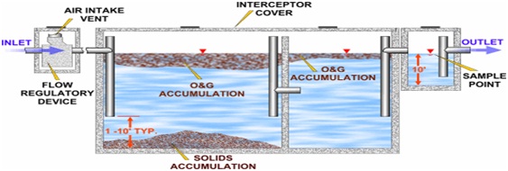
The oil & grease traps are to be located near the source contributing grease & oil to sewage. They are thus located at places like automobile garage, grease & oil producing industries, kitchens of hotels.
The following are reasons for excluding grease and oil from the sewage.
• If the grease & oil are allowed to enter the sewer, they stick to sides of sewer and consequently the capacity of sewers are reduced.
• The presence of grease & oil in the sewage also adds to the possibilities of explosion in sewers.
• The presence of grease & oil in the sewers is also objectionable from view point of treatment of sewage.
• The suspended matter which would otherwise have been conveyed also sticks to the side of sewers due to sticky nature of oil & grease.
The oil & grease traps should be carefully inspected & properly cleaned at regular intervals. If it is not done they will not functioned properly & there will not be a free flow of sewage.
Various gases are produced in the sewers due to decomposition of organic materials of sewage. These gases are foul in nature, cause harm to human health and corrode the sewers reducing their life. The gases so produced are highly explosive and in high concentration may cause fatal accidents to the maintenance people on duty due to their explosive and poisonous characters. Due to the above difficulties, ventilation is provided to the sewers lines at every 80-100 meters which will provide fresh air to the workers working in the manholes.
It may be of RCC or cast iron 15 to 23 cm in diameter with a cowl provided at the top. The ventilating shaft is generally connected to the manholes by 15 cm in diameter pipe. In open areas, the manhole covers may provided with vent pipes, but in crowed areas they should be air tight and connected with ventilating shaft.
In modern, well designed sewerage system, there is no need to provide ventilation on such elaborate scale considered necessary in the past specially with the present day to omit intercepting traps in house connections. The ventilating columns are not necessary where intercepting traps are not provided. It is necessary however to make provision for the escape of air to take care of the exigencies of full flow and also to keep the sewage as fresh as possible espically in outfall sewers. In storm water this can be done by providing ventilating manhole covers.
i. Soil engineering in theory and practice volume-3 by Alam Singh.
ii. Foundation analysis and design by Joseph.E.Bowles.
iii. Foundation design by Nainan.P.Kurian.
iv. IS 15284(part 1)-2003 design and construction for ground improvement- Guidelines (Part 1) - Stone columns.
v. IS 13094-1992 Ground improvement-techniques on weak soil.
| Are you interested in this topic.Then visit the below page to get the full report |
