


Published on Apr 02, 2024
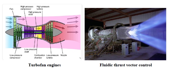
Thrust vectoring is the ability of an aircraft or other vehicle to deflect the angle of thrust away from the vehicles longitudinal axis. The concept of thrust vectoring is not a new one. The Germans used graphic control vanes in the exhaust stream of their V-2 ballistic missile in ww2 for directional control. Thrust vectoring in aircraft is a new practice and a concept came under widespread consideration during the cold war. There are several methods employed to produce thrust vectoring. Most current production aircraft with thrust vectoring use turbofan engines with rotating nozzles or turning vanes to deflect the exhaust stream. This method can deflect thrust to as much as 90 degrees providing a vertical takeoff and landing capability. However for vertical thrust the engine has to be more powerful to overcome the weight of the aircraft, this means the aircraft requires a bigger heavier engine. As a result of the increased overall weight of the aircraft the maneuverability and agility are reduced in normal horizontal flight. Another method to produce thrust vectoring is through fluidic thrust vector control. This is achieved using a static nozzle and a secondary flow between the primary jet and the nozzle. This method is desirable for its lower weight, mechanical simplicity and lower radar cross section.
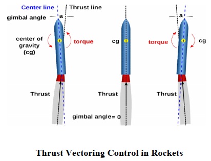
The thrust vector control history first came from rockets. The evolution of the rocket has made it an indispensable tool in the exploration of space. The ancient Chinese were the first to create rockets, but there use was confined to small fire works. Not until the 20th century did a clear understanding of the principles of rockets emerge, and only then did the technology of large rockets begin to evolve. Most math and physics used in spaceflight and rocket was developed in1650-1910. The first space engineer, Konstantian Tsiolkovsky (Russian, 1857-1935). he is the first to analyze rocket motion using. Newton’s Laws of Motion and wrote numerous technical papers describing artificial satellites, space stations, exploration of space, etc. Tsiolkovsky stated that the speed and range of a rocket were limited only by the exhaust velocity of escaping gases. For his ideas, careful research, and great vision, Tsiolkovsky has been called the father of modern astronautics. His engineering suggestions were foresighted and technically accurate that he suggested the use of thrust vectoring in rockets (aiming the rocket to steer the rocket) and the use of liquid fuels in the propulsions of rockets (prior to that time, only solid, dry chemical rockets had been built).
All chemical propulsion systems can be provided with one of several types of thrust vector control (TVC) mechanisms. Some of these apply either to solid, hybrid, or to liquid propellant rocket propulsion systems, but most are specific to only one of these propulsion categories. Thrust vector control is effective only while the propulsion system is operating and creating an exhaust jet. For the flight period, when a rocket propulsion system is not firing and therefore its TVC is inoperative, a separate mechanism needs to be provided to the flying vehicle for achieving control over its attitude or flight path.
Hence, there are two types of thrust vector control concept:
(1) for an engine or a motor with a single nozzle
(2) for those that have two or more nozzles
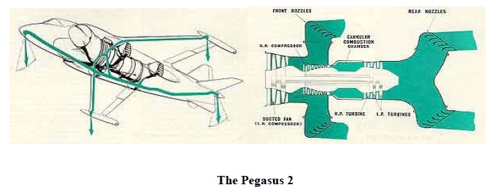
The vectored thrust story started in the mid 1950s when a Frenchman, Michel Wibault, proposed a single seat fighter that he called the Gyroptere. Wibault proposed to vector the thrust of four separate centrifugal blowers driven by a single 8000 HP Bristol Orion engine. He chose the Bristol engine because it was then the most powerful turbo-shaft engine in prospect. He was unable to interest the French authorities with this idea, but in 1956 he left a brochure with the US officer running the Paris office of the Mutual Weapons Development Programmed Colonel Chapman USAF. As Chapman was working on a engine called the Orpheus engine with Bristol Aero-Engines. Hence with there collaboration it led to a new Bristol engine, the Pegasus, having 4 rotating nozzle. By 1959 the Pegasus 1 was running on a Bristol test-bed and Hawkers were making the P1127 airframe.
In October 1960 Hawkers were ready to fly the first P1127. It was decided to look at the unknowns of hovering before flying the aircraft conventionally. The engine, by now the Pegasus 2 of 11,000lb thrust, was installed as shown in fig.2. The main characteristics were a large bifurcated intake and four swiveling exhaust nozzles interconnected together which enabled the thrust vector to be moved, as required, from 0 to about 18 degrees forward of the vertical. The figure shows the engine position in the jet.
Although the Harrier was the first who invented thrust vectored aircraft, for three decades Yakovlev design Bureau contacted the research-development-test evaluation works connected with creation of thrust vectored VTOL aircraft. The experimental aircraft Yak-36 permitted to accumulate the valuable experience in that field, and create the unique research facilities for that new technology in aviation in 1963. Many companies tried to solve the problems connected with this technology, but only two of the projects were carried to completion, serial production and operation: English "Harrier" and Russian Yak-38. In 1987, Russia has developed and tested the World first supersonic thrust vectored STOVL aircraft Yak-141. Whereas the first supersonic fighters in production that support thrust vectoring were Mikoyan Mig-29OVT, Sukhoi Su-35 and Sukhoi Su-30MKI. The best known example of thrust vectoring in an engine is the Rolls- Royce Pegasus engine of the Hawker-Siddeley Harrier brother to the BS100. (with variants built by McDonnell Douglas). The technique has been used in various experimental and development planes, some with vectored thrust in directions other than upwards. Widespread use of thrust vectoring for maneuverability in a Western fighter aircraft would have to wait for the 21st century, and the deployment of the Lockheed Martin F-22 Raptor fifth-generation jet fighter ( introduced in 2011), with its afterburning, thrust-vectoring Pratt & Whitney F119 turbofan. Shown below is a list of aircrafts with thrust vectoring capabilities of different era.
Historically Thrust Vectoring has mainly been used to provide a VTOL or STOL capacity in an aircraft. The high thrust to weight ratio of jet engines means vertical flight using thrust vectoring seems to be feasible. To date there are only two operational jet VTOL aircraft, the British Harrier and the Russian YAK-38. However providing a VTOL capacity often disadvantages maneuverability in horizontal flight, consumes large amounts of fuel and is a detriment to stealth. So recently there have been moves to use thrust vectoring in jet fighters just for a VSTOL capability or extra maneuverability in horizontal flight. Thrust vectoring for all these applications can be accomplished by using some of the following methods.
Tilt Prop- This type of aircraft tilts the engine and propeller assembly away from the horizontal to provide vectored thrust.
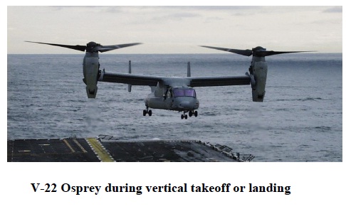
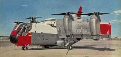
This design is similar to tilt prop, except rotors are used instead of propellers. An example of this type of aircraft is the V-22 Osprey used in military service for its VSTOL and medium weight lift capability. This aircraft also uses the deflected slipstream method to create lift when in horizontal flight.
Tilting the entire wing, instead of just the rotor or propeller, provides the benefit of increasing aerodynamic flow over the lifting and control surfaces during transition, and minimizes the lift loss due to downwash in hover. Disadvantages, however, are that an additional method of control such as a tail jet or rotor is required for control in hover, and ailerons change from roll control in horizontal flight to yaw control in hover. Control is especially difficult in hover during gusts due to the "barn door effect" of the wings in a vertical position.
The Propeller or Jet slipstream is deflected downward with the trailing flaps or a specially designed “bucket”, this vectors the thrust downward. This configuration is only useful for providing a medium STOL capability and in some experimental aircraft a VTOL capability. Some Military cargo planes use this design to enable shorter takeoffs on short “makeshift” runways and faster approaches for landing. The C-17 Globemaster III uses this technology to provide a medium STOL capability.
A number of VTOL propulsion concepts use a “split flow” engine to provide thrust vectoring. This involves a modification to a turbofan engine which splits airflow away from the core airflow and is used to provide a balanced thrust vectoring solution. The Harrier uses this concept in the Pegasus engine in which the fan air and core air are exhausted separately through elbow nozzles. This concept is also good for thrust vectoring in horizontal flight. The problem with this design is that the engine must placed at the cg of the aircraft, this means the middle section of the aircraft needs to be wider to accommodate the engine. Having a wider mid section increases supersonic wave drag. This means designing a supersonic aircraft with thrust vectoring using this design is very difficult. The picture shows separate ducting of fan and core air.
For thrust vectoring to occur the jet exhaust has to be turned somehow. This can be achieved using mechanical or fluidic means.
Mechanical thrust vectoring is achieved by mechanically deflecting the exhaust flow of an aircraft using some sort of physical object. This is usually achieved using various nozzles or vanes.
Flaps deflect the engines flow in much the same way as wing flaps deflect the external air flow see figure 15a This type of system introduces a thrust loss of approximately 3-6% when vectored to 90 degrees. The vectoring flaps can also be external to the nozzle as a part of the wing flap.
The bucket thrust vectoring mechanism is similar to the commonly used clamshell thrust reverser see figure 15b. The great advantage to this concept is that all the force is transmitted through the hinge line of the bucket meaning actuators can be reasonably small. Another advantage of this system is that the turning surface can be made very efficient. This method can be used to create 90 degree vectoring with about 2-3% thrust loss.
In this type of nozzle (figure 15c) the tailpipe is broken along slanted lines into three pieces as shown. The three pieces are connected with circular rotating-ring bearings so that the middle (shaded) piece can be rotated about its longitudinal axis while the other parts remain un-rotated. This causes the middle and end parts of the nozzle to vector thrust downward. This vectoring nozzle has a 3-5% thrust loss when vectoring at 90 degrees.
The ventral nozzle (figure 15d) is simply a hole in the bottom of the tailpipe leading to a downward facing nozzle. The normal exhaust opening is blocked by some sort of valve. These valves can be used easily on aircraft with afterburners because they can be placed upstream of the afterburner. These ventral nozzles can help solve the balance problem of VTOL aircraft. The ventral nozzle has a thrust loss of 3-6% when vectored to 90 degrees.
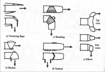
This type of nozzle is used on the AV-8 Harrier. The elbow nozzle is simple and lightweight and doesn’t require much actuating force. A disadvantage of this design is the fact that the flow is always being turned through a total of 180 degrees, even in forward flight. Because the flow is always being turned this nozzle type suffers 6-8% thrust loss at all times. All the other types of vectoring nozzle only impose a thrust loss during vertical flight. Usually a combination of any of these nozzles has the best effect for a particular aircraft design.
Thrust-vectoring research to date has successfully identified and demonstrated many potential benefits to high-performance aircraft. These include enhanced aircraft maneuverability, performance, survivability, and stealth. The full extent of these benefits, however, has yet to be realized even with new generation aircraft because current mechanical thrust-vectoring configurations are heavy, complex, and expensive.
A requirement of modern warfare is the improvement of maneuverability and control capabilities which TVC provides. The agility of aircraft can be determined by such things as pitch, roll and yaw rates, acceleration and deceleration and turning ability.
Aircraft that have small take off and landing zones are largely advantageous as it reduces the space required for operation of the aircraft. This allows the aircraft to operate in more compact environments such as aircraft carriers and airports, which as a result may decrease the size of such things, or allow more aircraft to occupy the same space as a non STOL capable aircraft.
As evident in figures five and six, an aircraft with TVC requires less thrust to achieve desired results such flight regimes as cruise, climb and decent. This has the effect it reduces the fuel consumption of the aircraft due to the lower thrust requirement, which in turn increases the aircrafts flight range.
Using the theory that thrust vectoring can supplement control surfaces, it has been shown that thrust vectoring has the ability to provide a “tailless” aircraft. On these tailless aircraft vectored thrust provides engine-based flight control. The benefits of reduced dependence on a rear tail are reduced drag, reduced aircraft weight, and less radar cross section. These tailless designs are therefore stealthier than other conventional designs.
Trust Vector control does have its disadvantages and limitation. Implementation of TVC increases the weight of the aircraft, due to its complexities can also inhibit the performance of the aircraft, increases the cost significantly and can also not meet other requirements of the aircraft such as the cost, stealth performance criteria required of the particular aircraft.
Thrust vectoring is becoming more and more prevalent in aircraft as its benefits become more useful and efficient and as new and improved ways of vectoring thrust become available. Thrust vectoring is most commonly known in the harrier jet for its obvious implication of the aircrafts ability for vertical takeoff and landing, however there are many other examples of thrust vector control not only in aircraft but rockets as well. However the harrier was the first and only successful aircraft with thrust vectoring used for V/STOL capabilities until modern aircraft such as the future released F-35. The problems and difficulties of incorporating thrust vectoring in aircraft is a contributing factor as to why more aircraft in the 20th century didn’t employ thrust vectoring. The harrier as an example has the Rolls Royce Pegasus engine which is a split flow style engine with four elbows nozzles. The engine was used as it provides the required thrust for V/STOL capabilities, however it is quite large and heavy, and the engine must be placed at the center of gravity of the aircraft which intern widens the aircraft and reduces achievable airspeed and agility.
These inferiorities compared to other non thrust vectored aircraft would have contributed to the slow appearance of similar features in future aircraft due to its inability to include maneuverability, higher speeds partnered with thrust vectoring, as well as perhaps the harrier meeting all requirements asked of it and it being sufficient for the times. Another example is the C-17 Globemaster III airlifter that deflects the jet slipstream with the trailing flaps which vectors the thrust downwards useful for shorter take off than otherwise it being absent. Thrust vectoring is becoming more and more prevalent in new aircraft such as the indevelopment F-35 and F-22. Due to the advances in thrust vector control since the era of the Harrier aircraft, new aircraft can incorporate thrust vector control and still maintain and improve on such things as maneuverability and stealth attributes.
The shorter takeoff range, longer flight range, higher maneuverability that these new aircraft with thrust vectoring posses are much valued when compared to other and older aircraft. The ability to out maneuver an opponent, travel further, takeoff and land faster in smaller areas are all major features that new thrust vectored control aircraft posses. As thrust vector control systems become less expensive, less heavy and complex, such as is the case with Fluidic Thrust Vectoring methods, thrust vectoring will become a required feature of a fighter jet at least, to still be able to compete with other thrust vectored aircraft. Of course, these improvements are not exclusive to fighter jets, but also other aircraft as outlined earlier such as cargo aircraft such as the C-17 Globemaster.
Although thrust vectoring is not a new concept, modern advancements in thrust vectoring have made it quite conceivable that in the future a much higher percentage of aircraft will posses thrust vector, not only military aircraft but also other aircraft such as perhaps passenger aircraft, cargo aircraft, as its benefits are not exclusive to military applications, but many more forms of aircraft. With the several different ways to implement thrust vectoring such as Fluidic, mechanical, split flow or separate engines, there are suitable options for its implementation in a range of different types of aircraft.
“Thrust Vectoring”, Wikipedia
http://en.win.kipedia.org/wiki/
“Pitching Moment”, Wikipedia
http://en.win.kipedia.org/wiki/
“Vectored Thrust”, NASA
http://www.lerc.nasa.gov/WWW/K-12/airplane/vecthrst.html
“AV-8B Harrier History”
http://www.globalsecurity.org/military/systems/aircraft/av-8-history.htm
“History of Spaceflight”, 2006
http://www.courses.psu.edu/aersp/aersp055_r81/history.html
“Konstantin Tsiolkovsky”, 2006
http://en.wikipedia.org/wiki/Konstantin_Tsiolkovsky
"Rocket" Microsoft Encarta Online Encyclopedia 2006
http://encarta.msn.com/encnet/refpages/RefArtTextonly.aspx?refid=761577900&print=0
| Are you interested in this topic.Then visit the below page to get the full report |
