


Published on Apr 02, 2024
The objective of the assisted machining techniques is to improve the cutting process by acting on the chip removal mechanism. Nowadays, based on their feasibility and industrial expectations there are two most techniques used, they are Jet Assisted Machining (JAM) and Thermal Enhanced Machining (TEM). In Jet Assisted Machining a high velocity jet stream of materials is directed Thermal Enhanced Machining- conventional cutting process in which an external energy source is used to enhance the chip-generation mechanism to impact on the work piece surface to achieve the required machining process. The cutting process takes place at temperatures ranging from 400° to 700°C, and therefore the shear strength of the material is significantly lower than the room temperature strength, resulting in considerably lower cutting forces. The technique is economically feasible only when the machinability of the material being processed is limited and therefore the cutting parameters depth of cut, feed per tooth and cutting speed are very low.
This is the case of the heat resistant alloys, such as the Ni-base alloy Inconel 718 (standard AMS 5596, UNS N07718, 52Ni-19Fe-18Cr-5(Cb1Ta) -3Mo-0.9Ti-0.5Al ) and the Co-base alloy Haynes 25 (standard AMS 5537, L605, UNS R30605, 51Co-20Cr-15W-10Ni-1.5Mn-0.10C-3Fe-0.4S).These materials maintain their mechanical properties as well as an excellent corrosion resistance even over 600°C. Because of these properties, above materials have been used in the manufacturing of the turbine components of both commercial and military airplane engines.
The machine consists of two unit’s i.e. the plasma production unit and the milling unit. The high energy plasma is utilized for thermal softening of the material followed by milling operation. The following figure shows a schematic drawing of the plasma-machine system layout. Fig 1 Plasma assisted milling Heated spot by the plasma jet is a circle of maximum heating, where the temperature is between 500°C and 1,000°C.The energy is transferred to the work piece by convection process and the adjacent zone, where the heat is transferred by conduction . The heat distribution on the surface is supposed to follow a Gauss distribution. The nozzle is focused at a distance of about 8 ±10 mm ahead of the milling tool in the direction of the feed. This distance is high enough to prevent the tool body from being directly affected by the plasma jet.
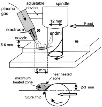
The nozzle is placed at a height of 5-6 mm over the work piece and thus the electric arc responsible for the ionization of the channel known as transferred arc can be activated. The diameter of the heated spot is about 4-5 mm. The spot must be located just exactly at the material to be removed thus avoiding the zones of the work piece previously machined. The geometry of the work piece must be simple with geometrical features that do not involve sharp changes in the feed direction, since the plasma spot must be located ahead of the tool during the whole process. The ionized gas produces material surface heating by convection. The result is a phenomenon known as thermal softening, which is related to the reduction of the cutting forces.
Plasma assisted milling is recommended for the machining of low-machinability alloys, and especially those whose mechanical properties decrease only over a certain temperature. In these materials a high mechanical strength is related to high shear strength and therefore machining is difficult. The Ni-base and Co-base alloys are considered to be amongst the materials with lowest machinability. This low machinability depends mainly on the following factors:
• The cutting forces and the temperature at the cutting zone are extremely high. This is due to the heat generated by the high deformation energy, as well as to the low thermal conductivity of these materials.
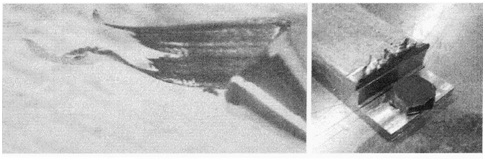
• Ductility-the machining of ductile alloys requires very sharp cutting edges with a positive rake angle. For the operation to be a cutting process rather than a plowing action. However, these materials must be machined with strong tools with low rake angles because of their high specific cutting energy. The high ductility is responsible of the some frequent chip type named ``chipfoot,'' when the tool exits from the work piece; at this point the material is stretched rather than cut. This produces an uncontrolled chipping of the tool edge. Figure below shows an Inconel chip-foot and the burrs on the edges of a Haynes 25 work piece that also related with material ductility
• Strain hardening-This phenomenon is caused by the cold working of the material during the plastic deformation inherent to the cutting process. It is closely related to the metallurgical structure of materials. In this case related to the austenitic matrix of Inconel 718 alloy and the g phase of Haynes 25. In order to reduce it, very small feed, high cutting speed and worn tools must be avoided. Cold working of the machined surfaces related to the increase in hardness makes future operations more difficult, causing premature notch wear of the tool at the point of the edge intersecting the work surface
Plasma assisted machining could be applied to Ti-base alloys such as the Ti6Al4V alloy which is a very popular material in the aerospace industry. This material exhibits a very low machinability. But for these materials machining problems arise from the high temperatures in the tool/ chip contact area due to the low thermal conductivity of the alloy. These alloys also present high chemical reactivity at the temperatures (500°) induced in the tool/chip interface during the cut-ting process with almost all tool materials. These facts drive to a quick tool wear.
Inconel 718 alloy has high corrosion resistance and high strength with outstanding weldability including resistance to post weld cracking. This alloy has excellent creep-rupture strength at temperatures up to 700°C. Haynes 25 has excellent high-temperature strength with good resistance to oxidizing environments up to 980°C for prolonged exposures and excellent resistance to metal galling and it is also very sensitive to cold working. The alloy Ti6Al4V is an Alfa-beta alloy used in the cold parts of turbines.
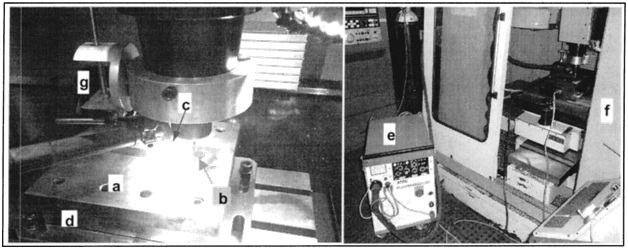
Machine setup is a three axis conventional machining center equipped with a spindle with rotational speed below 10,000 rpm and maximum linear feed of 5 m/min.The NC unit controls the machining tool paths and the basic operation of the plasma power generator, using specially programmed miscellaneous M type functions. Thus the pilot and the transferred arcs can be switched on/off. The following figure shows the machine setup of PAM process.
The nozzle is focused at a distance of about 8 ±10 mm ahead of the milling tool in the direction of the feed. This distance is high enough to prevent the tool body from being directly affected by the plasma jet. The nozzle is placed at a height of 5-6 mm over the work piece, and thus the electric arc responsible for the ionization of the channel known as transferred arc can be activated. The diameter of the heated spot is about 4-5 mm. The spot must be located just exactly at the material to be removed, avoiding the zones of the work piece previously machined.
The temperature of the ionized gas Argon is well over 15,000 K. The velocity of the plasma jet about 5 mm away from nozzle is 400 m/s and at this is the speed at which the plasma jet impacts on the material surface. The energy is transferred by convection to the work piece and produces the heating of the work surface at temperatures ranging from 400 to 1,000°C. The heating of the work piece depends primarily on two operating parameters one is the intensity of the transferred arc I and the translational velocity of torch over the work surface in case of milling because of the location of the nozzle fixed with respect to the milling tool. The velocity is equal to the machine-tool linear feed F .
The most used tools for this process are sintered tungsten carbide ones (grade K5-K10) coated with TiAlN or TiCN with very moderate cutting conditions. An alternative solution is the use of more expensive tools such as PCBN ~Polycrystalline Cubic Boron Ni-tride as well as whiskers reinforced ceramics (Al2 O 3 1CSiw).
In Plasma Assisted Milling different technical inputs must be taken into account to adequately select the cutting parameters
• The process parameters f z and a e are related to the size of the heating spot. The machine linear feed F is directly related to the heating of the work surface. The axial depth of cut a p depends of the temperature gradient under the surface due to the plasma heating.
• The cutting conditions f z , Vc , a p and a e have a direct influence on the tool behavior and process performance. There is a cross relationship between the machine parameters ( F , S , a p and a e ) and the heating parameter F . The relation of these parameter is shown as F=( fz 1000 V c z)/ (∏ D), were a e radial depth of cut, a p axial depth of cut, V c cutting speed, f z = feed per tooth, z = no of teeth of tool
• The values for tool diameter D have been selected as a function of the plasma spot size 3-4 mm. Thus, in the case of solid carbide tools, 12 mm diameter tools have been used. In the case of insert tools, 50 mm diameter tools with round inserts of 12 mm diameter were selected. An adequate selection of z allows the selection of a wide range of values for the feed per tooth f z and the cutting speed V c.
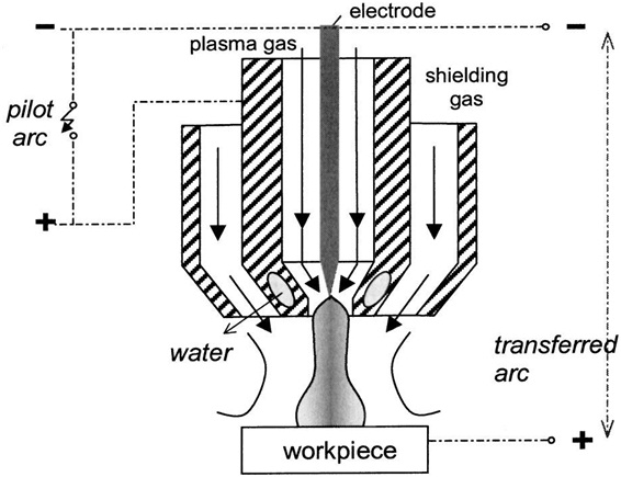
The plasma power equipment is a commercial welding one, providing transferred arcs direct current at a maximum intensity of 250 A. The plasma torch is a copper nozzle of 2 mm diameter. Tungsten electrode cathodes with 30° taper angle are used. The plasma gas is Argon with a flow of 0.5 l/min, while the shielding gas is a mixture of Argon and 5% of Hydrogen, with an approximate flow of 11 l/min. The nozzle serves as anode when used with nonconductive materials, while the arc is transferred to the work-piece in the case of conductive pieces. A picture of the plasma torch is shown in the following figure.
The nozzle is placed 5-6 mm over the work piece. The heating of the work piece depends primarily on two operating parameters one is the intensity of the transferred arc I and the translational velocity of torch over the work surface in the case of milling, because of the location of the nozzle fixed with respect to the milling tool.
Plasma is a superheated, electrically ionized gas flow. The plasma power generator consists of a power supply, an arc starting circuit and a torch. Plasma arc generated between electrode in torch and anode work piece the plasma flows through water-cooled or gas cooled nozzle that constricts and directs stream to desired location for heating. The arc starting circuit is a high frequency generator circuit that produces an AC voltage of 5,000 to 10,000 volts at approximately 2 megahertz. This voltage creates a high intensity arc inside the torch which ionize the gas and thereby producing the plasma. Once the gas flow is stabilized the high a.c voltage breakdown is applied and thus producing the arc between the electrode and nozzle. The flow of the gas forces this arc through the nozzle orifice and thus creating the pilot arc .when the pilot arc comes in contact with the work piece surface the system shutdown the a.c supply and the pilot arc is maintained with a d.c supply .Thus the process of heating the work piece surface using plasma jet is carried out.
Ti6Al4V, a difficult to cut material used in aircraft engines is used for the study of PAM process and the results obtained are
The temperature 1 mm below the work surface has been analyzed. Thus, when using a plasma intensity of 30 A the temperature is 171°C, whereas in the case of 60 A the temperature is 247°C. These values are lower than those measured in the case of Haynes 25 or Inconel 718. This is due to the low thermal conductivity of titanium, nearly 35% less than the heat-resistant alloys. This results about temperature shows that clearly there is a reduction in cutting forces associated with the PAM process on Ti6Al4V material.
The tool’s flank wear rate is found to be increasing with the plasma arc intensity. The reason is again the low thermal conductivity of titanium than the heat-resistant alloys .Due to which a high heat concentration on the surface is formed. This is why the tool section in contact with the surface suffers a more rapid degradation.
The metallurgical structures of Ti6Al4V after heating and after PAM heating and machining have been analyzed. The main conclusion is that material melting in the heated zone always happens, even at low plasma intensity or high linear feed due to the very low thermal conductivity of titanium. Melting of the material has been detected in all the tests arc intensities from 25 to 60 A together with a small zone of transition between the heated and the not-heated zones.
For all the materials used for the study, it is found that there is considerable reduction in cutting forces. This due to thermal softening of the materials resulted from the plasma jet heating. For Haynes 25, Inconel 718 we can see that the tool wear rate is reduced considerably compared with the conventional type of machining,so the technique of plasma assisted machining is very much recommended for the machining of these two HRSA materials. But for the titanium alloy it is found that the PAM process shows negative results because of the melting of work piece surface and higher tool wear rate. This due to very low thermal conductivity of Ti6Al4V than HRSA . For any material the technique of PAM is economically feasible only when the machinability of the material being processed is limited.
• Weinert, K., 1994, ``Relation between Process Energy and Tool Wear when Turning Hardfacing Alloys,'' CIRP Ann., 43~1!, 97-100
• Novak, J. W., Shin, Y. C., and Incropera, F. P., 1997, ``Assessment of Plasma Enhanced Machining for Improved Machinability of Inconel 718,'' ASME J. Manuf. Sci. Eng., 119, pp. 125±129.
• Kitagawa, T., and Maekawa, K., 1990, ``Plasma Hot Machining for New En-gineering Materials,'' Wear, 139, pp. 251±267.
• Leshock, C. E., Kim, J. N., and Shin, Y. C., 2001, ``Plasma Enhanced Machin-ing of Inconel 718: Modelling of Workpiece Temperature With Plasma Heating and Experimental Results,'' Int. J. Mach. Tools Manuf., 41, pp. 877± 897.
• KoÂnig, W., CronjaÈger, L., Spur, G., ToÂnshoff, H. K., Vigneau, M., and Zdebe-lick, W. J., 1990, ``Machining of New Materials,'' CIRP Ann., 39~1!, pp. 673± 681
| Are you interested in this topic.Then visit the below page to get the full report |
