


Published on Apr 02, 2024
A Hydrofoil is a specially designed hydrodynamic surface that creates lift significantly exceeding drag. The main function of the hydrofoil is to lift the ships hull out side the water. At low speeds the ships hull sits on the water and the hydrofoils are totally submerged in water, but as the speed increases the hydrofoils create lift, bringing the hull outside the water surface.
The basic principle of the hydrofoil concept is simply to lift a ship's hull out of the water and support it dynamically on wing-like lifting surfaces, i.e. hydrofoils, to reduce the effect of waves on the ship and to reduce the power required to attain modestly high speeds. Engineers and naval architects have been intrigued with the possibilities of this concept for many years. A United States patent for a hydrofoil was defined in the late 1880s, about the same time as the early airplane and airfoil patents. The earliest record of a successful hydrofoil flight is 1894 when the Meacham brothers demonstrated their 14 foot test craft at Chicago, Illinois.
This compares with the Wright brothers' first airplane flight in 1903. The early attempts to exploit the hydrofoil concept were frustrated by lack of suitable structural materials and power plants. However, advancement in these areas, much of it stemming from aircraft developments, has permitted development over the past 30 to 40 years of the technology necessary to achieve and demonstrate reliable and effective hydrofoil ships for both military and commercial below.
Many people are familiar with airfoils. Foil is simply another word for the wing (such as the wing on an airplane). A hydrofoil is a wing that 'flies' in water. Hydrofoil is also used to refer to the boat to which the water wings are attached. A hydrofoil boat has two modes of operation:
a. as a normal boat with a hull that displaces water and
b. with the hull completely out of the water and only the foils submerged.
Hydrofoils let a boat go faster by getting the hull out of the water. When a normal boat moves forward, most of the energy expended goes into moving the water in front of the boat out of the way (by pushing the hull through it). Hydrofoils lift the hull out of the water so that you only have to overcome the drag on the foils instead of all of the drag on the hull.
The foils on a hydrofoil boat are much smaller than the wings (foils) on an airplane. This is because water is about 1000 times as dense as air. The higher density also means that the foils do not have to move anywhere near as fast as a plane before they generate enough lift to push the boat out of the water.
The hydrofoils generate lift only when they are in the water; if they leave the water, the boat will crash down onto the surface of the water (and thus submerge the foils) until the foils generate enough lift to lift it back out. Like an airplane, a hydrofoil must be controllable in terms of pitch, roll, and yaw. Unlike an airplane, a hydrofoil must also maintain a consistent depth. Whereas an airplane has a range of about 40,000 feet in which to maintain its altitude, a hydrofoil is limited to the length of the struts, which support the boat above the foils.
1. At low speeds the hull (body of ship) sits in the water and the hydrofoils are totally submerged in the water.
2. As the boat's speed increases, the hydrofoils create lift.
3. At a certain speed, the lift produced by the hydrofoils equals the sum of of the boat and cargo weights. Therefore the hull comes out of the water.
4. Instead of having an increase in drag with increasing speed because the hull is lifted out of the water (contrary to what happens in traditional boats due to pressure drag), the hydrofoils provide a more efficient way of cruising. Decreasing the drag contributes to the better use of the power needed for the movement of the boat.
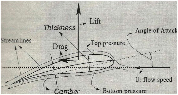
This equation applies to flows along a streamline which can be modeled as: inviscid, incompressible, steady, irrotational and for which the body forces are conservative. Also the difference on the height of the foil (the distance from the bottom section to the upper one) is small enough so that the difference pgy2 – pgy1 is negligible compared to the difference of the rest of the terms. What is left is that the pressure plus one half the density times the velocity squared equals a constant (the stagnation pressure).
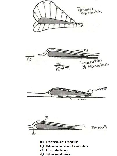
As the speed along these streamlines increases, the pressure drops (this will become important shortly). The fluid that moves over the upper surface of the foil moves faster than the fluid on the bottom. This is due in part to viscous effects, which lead to formation of vertices at the end of the foil. In order to conserve angular momentum caused by the counter-clockwise rotation of the vortices, there has to be an equal but opposite momentum exchange to the vortex at the trailing edge of the foil. This leads to circulation of the fluid around the foil. The vector summation of the velocities results on a higher speed on the top surface and a lower speed on the bottom surface. Applying this to Bernoulli's it is observed that, as the foil cuts through fluid, the change in velocity produces the pressure drop needed for the lift. As it is presented in the diagram, the resulting or net force (force= i pressure) (area)) is upward.
a) Pressure Profile
b) Momentum Transfer
c) Circulation
d) Streamlines
This explanation can be enriched with the Principle of Conservation of Momentum. (Momentum = (mass) (velocity)) If the velocity of a particle with an initial momentum is increased, then there is a reactant momentum equal in magnitude and opposite in direction to the difference of the momentums.
(Mi = Mf + C1M)
At first, people can think that stalling is likely to be a problem in hydrofoils as it is in airfoils, but surprisingly it is not. A steep angle of attack is not needed in the design of the hydrofoil. On the contrary, small angles of attack are used on hydrofoils to optimize the lift to drag ratio as explained before.
What is a primary concern is the design of the foil, the struts/supports, and their positioning. All these features have to be taken in consideration. So the features are designed to produce a minimum speed that will lift the boat of certain weight and keep it foil borne.
One problem that a hydrofoil craft can experience is the height of the waves being greater than the struts. Also, if the craft is traveling faster than the waves, the foils could break to the surface and outside of the water, resulting in a loss of lift and a negative angle of attack when the foil dives into the next wave, making the craft crash into the sea. Engineers have designed hydrofoils to minimize these limitations and better the ship's performance.
There are two particularly persistent problems faced by designers of hydrofoils:
Ventilation occurs when part of a hydrofoil pierces the surface of the water and air gets sucked down the lifting surface of the foil. Since air is much less dense than water, the foil generates much less lift and the boat crashes down. Ventilation can occur at any air-water interface.
Ventilation occurs when air gets sucked down to the lifting surfaces. Although ventilation can occur on -vertical struts, 'V foils are particularly prone to this problem because of the shallow angle the foil makes with the water surface.
Cavitation occurs when the water pressure is lowered to the point where the water starts to boil. This frequently happens with propellers. When a propeller is turned fast enough, the blades generate so much lift (i.e. the pressure on the lifting surface of the blades goes down) that the water flowing over the propeller blades begins to boil. When cavitation occurs, the foil no longer generates enough lift and the boat crashed down onto the water.
Note that a hydrofoil is not a hovercraft. Hydrofoils fly on wings in the water that generate lift whereas hovercraft floats above the water on a layer of air. In both cases the boat's hull leaves the water, but the mechanisms by which this is achieved are completely different
Hydrofoil configurations can be divided into two general classifications, surface piercing and fully submerged which describe how the lifting surfaces are arranged and operate (see Figure 1). In the surface piercing concept, portions of the foils are designed to extend through the air/sea interface when foil borne. Struts connect the foils to the hull of the ship with sufficient length to support the hull free of the water surface when operating at design speeds. As speed is increased, the lifting force generated by the water flow over the submerged portion of the foils increases causing the ship to rise and the submerged area of the foils to decrease. For a given speed the ship will rise until the lifting force equals the weight carried by the foils. As indicated by the terminology, the foils of the fully submerged concept are designed to operate at all times under the water surface.
The struts which connect the foils to hull and support it when the ship is foilborne generally do not contribute to the total hydrofoil system lifting force. In this configuration, the hydrofoil system is not self-stabilizing. Means must be provided to vary the effective angle of attack of the foils to change the lifting force in response to changing conditions of ship speed, weight and sea conditions. The principal and unique operational capability of hydrofoils with fully-submerged foils is the ability to uncouple the ship to a substantial degree from the effect of waves. This permits a relatively small hydrofoil ship to operate foilborne at high speed in sea conditions normally encountered while maintaining a comfortable motion environment for the crew and passengers and permitting effective employment of military equipment. It is this desirable characteristic which has caused the hydrofoil ship development in the United States to concentrate on the fully- submerged foil concept.
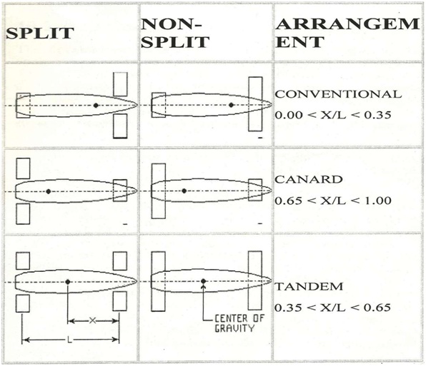
The basic choices in foil and strut arrangement are canard, conventional or tandem as shown in Figure 2. Generally ships are considered conventional or canard if 65°/o or more of the weight is supported on the front or the aft foil respectively. If the weight were distributed relatively evenly on the fore and aft foils, the configuration would be described as tandem.
As noted earlier, surface-piercing hydrofoil configurations are self-stabilizing in both pitch and roll and thus do not require an automatic control system. However, to reduce the inherent reaction to rough seas, a number of ships have added trailing- edge flaps to the surface-piercing foils and have used autopilots for ride improvement.
In the United States, full automatic control of submerged foils has been deemed necessary to attain the seaway performance desired for ocean-going hydrofoil ships. Typically, control is accomplished by positioning trailing-edge flaps on the forward and after foils and by rotating the swiveled forward strut (rudder), or by moving the entire foil surface and by using the power driven aft strut as a rudder. See Figures 9 and 10 for schematic and pictoral diagrams of a control system.
The control surfaces are positioned by means of conventional electro- hydraulic servos. The control system motion sensors consist of:
1) a vertical gyro which measures craft pitch and roll angular motion,
2) a rate gyro which measures craft yaw rate,
3) three vertical accelerometers, one accelerometer being located approximately on top of each strut (the two aft accelerations work differentially to provide roll angular acceleration feedback, and they work in unison to provide pitch and heave acceleration feedback), and
4) a height sensor which measures the height of the bow above the water surface.
The manual inputs consist of a foil depth command, which the helmsman uses to select any desired foil depth (or flying height), and the helm, which introduces the craft turning commands.
The ACS provides continuous control during takeoff, landing, and all foilborne operations. The pitch, roll, and height feedback loops provide automatic stabilization of the craft. The craft is automatically trimmed in pitch by the pitch feedback, and roll trim is accomplished by helm inputs. To steer the ship, the helmsman simply turns the helm, and the ACS automatically maintains a coordinated turn, with turn rate being proportional to helm deflection
1. A hydrofoil requires only 50°/o of the power of a displacement vessel of comparable size, for a given speed
2. The hydrofoil due to their small size and maneuverability, are target less vulnerable to tactical military weapons like missiles
3. Greater platform stability and high speed
4. Can be maintained even in seaway due to better sea keeping ability
Hydrofoils have become very popular. They are used in various kind of sea traveling, from military use to water sports. The high speed, smooth cruise and better turns delivered by hydrofoils have been used in military ships. Sailing has also adopted the hydrofoils to gain more speed. They enable new inventions that can satisfy people's desire to challenge danger, like the sky ski. It is a water ski with a hydrofoil attached, which permits people to fly above the water surface. Every day more hydrofoils are used, and in the future, they may be the dominate method of sea traveling
Although the basic concept of hydrofoils has been around for 85 years, it has only been in the last 35 years through advances in materials, light weight propulsion plants, and control theory, they have become a viable open ocean concept. Involved. The design of a hydrofoil demonstrates the very essence of engineering that is the trade-off and compromise among often-conflicting requirements of many disciplines to arrive at a good balanced design.
http://www.foils.org
www.howstuffworks.com
| Are you interested in this topic.Then visit the below page to get the full report |
