

Published on Nov 30, 2023
Vehicle accidents are ubiquitous in recent years. This is because of heavy increase in population of vehicles, due to its high demand. They pose a serious threat to life and property. A system must be designed to minimize the effects of these accidents. The aim of the present study is to design a device which can successfully scan the surroundings during driving and apply brake to avoid front end collision of the vehicle, along with extension of bumper. Ultrasonic sensor provided on the front end of the vehicle detects the presence of the obstacle. The data from the sensor is an input to the microcontroller. Microcontroller 8051 decodes the logic and generates appropriate control signals for the activation of driver alert mechanism, along with automatic actuation of pneumatic braking circuit and pneumatic bumper circuit. Pneumatic braking circuit applies brake and bring the vehicle to halt, and the latter one provides the safety of vehicle during impact. Driver alert mechanism is included to alert the driver at a safe braking distance from collision. All of these are integrated in a single system to provide for maximum protection of passenger, vehicle and property.
Vehicles are the revolutionary invention of mankind. With innovations in technology, they made their impression, in every aspects of life. Inflating demand for vehicles has led to substantial increase in number of vehicles. Although they can easily be learnt, we cannot exculpate the consequences due to negligence. Safety of the vehicle is a major concern even from the design stage of the vehicle. Several technologies like seat belts and air bags have successfully worked out well in accidental situations and proved to be useful. Automated collision avoidance system is one among such system to avoid the severity of accidents. It is an electrically controlled pneumatic circuitry, which aims to avoid forward collision of the vehicle and improve crashing safety. This is achieved by means of automatic pneumatic circuits. The system senses the obstacle by means of high frequency Ultrasonic waves and calculates the distance between the obstacle and vehicle.
Forecast of collision is tracked and an alert warning is given to the driver of the upcoming collision. These warnings are provided at a safe braking distance from the obstacle. The driver is alarmed twice at a distance of 125cm and 80cm respectively. On further delay the microcontroller signals for the actuation of pneumatic braking circuit and pneumatic bumper circuit simultaneously. Combination of these circuits effectively avoids collision and reduces the damage to be incurred by the vehicle. The first innovation in collision avoidance system was reported in 1989, where advanced brake warnings were implemented to warn the drivers of upcoming collision. Collision avoidance paved its way in 1995 by a team of scientists and engineers in Hughes Research Laboratories. Manufacturers such as Audi, BMW, and Honda have introduced medium frequency sensors and camera vision to detect the advancing collision.
With the use of suitable high frequency sensors, response time can be decreased thus giving more provision for the system to actuate. Vehicle safety can be improved by means of extendable bumper that can absorb more shock waves on collision. In the present study a model was designed to automatically forecast upcoming collision and take appropriate action and avoid collision by automatic braking and thus reduce the damage by automatic bumper circuit and to decrease response time by using high frequency waves. A safety system was designed to reduce property damage and passenger injury.
All the conventional vehicles are equipped with brakes that are operated manually. The consequence of collision depends on driver’s reflex to vary the driving environment. Vehicle accidents might be a consequence of rash driving, driving under influence, fatigue etc. Most of these can be mapped down to a single cause, driver’s inability to hit the brakes at right time. If this work is replaced by automatic means, most of the collision can be controlled. Vehicles are protected by a rubber padding mounted on front end of vehicle that absorbs shocks on collision. Most of these are static bumpers, where it has got no degree of freedom. Reducing a constraint by limiting its movement to a single direction can help to absorb more shocks on sudden impact, thereby decreasing effect of collision.
Compressed air has the ability to undergo an impact work. Pressure difference in two boundaries leads to flow of compressed air automatically. Working fluid used is air because it is readily available and abundant in nature. It can transmit impact load with a good degree of effectiveness, leakage problems won’t be hazardous and maintenance of the system is easy.
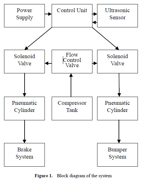
Air is compressed in the range of 4 to 4.5 bars. An ultrasonic sensor is provided in the front end portion of the vehicle the ultrasonic module includes transmitter, receiver and control circuit. Emitter continuously sends ultrasonic waves and waits for it to return back. In case of an obstacle present in the path the waves are reflected back to the device to be sensed by the detector. The time taken by ultrasonic waves to reflect back to the detector is computed to find the distance from the obstacle. On a forecast of crash, microcontroller 8051 controls buzzer to alarm the driver. If the driver still doesn’t respond to hit the brakes, microcontroller 8051 sends current through the relay to actuate the electromechanical actuator. The flow of compressed air occurs when solenoid valve is activated. Air enters from the compressor tank to the single acting cylinders. One end of the single acting cylinder is connected to disc brakes of the model and the other is connected to an extendable bumper which absorbs energy due to collision. The actuation of the brake and bumper occurs simultaneously. Compressed air must flow through polyethylene tubes before entering the cylinder to maintain the pressure along the lines.
Brakes are used to standstill a moving vehicle. They convert frictional energy to heat energy. To ensure a complete halt proper braking distance needs to be calculated. The governing equation to calculate the braking distance is given by
![]()
The model is expected to weigh around 30kgs on its completion. Model is to be designed for a speed of 8km/hr. The coefficient of friction between the road and tyre is taken as 0.8 and g represents acceleration due to gravity. On computing the given equation for the given condition a distance of 32 cm would be enough to ensure complete standstill
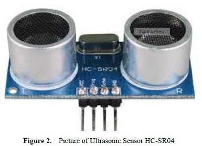
Ultrasonic sensing module equipped with emitter and detector integrated along with timing unit is used for pulse detection (Fig.2). It detects in proximity range from 2cm-400cm and has an accuracy of 3mm.The basic principle of work is, it uses IO trigger for 10μs high level signal. Modules automatically send eight 40 kHz and detect for pulse signal and note down the time taken for waves to bounce back.
Test distance = travel time × velocity of sound (2) Velocity of sound = 340m/s.
The parameters used in the sensor are working voltage, current, frequency of 5V, 15mA and 40 kHz respectively, aperture angle of 15 degree, dimension 45×20×15mm and trigger input signal of 10μs TTL pulse
Microcontroller is a highly integrated chip and is designed for specific embedded applications. This includes a CPU, RAM, I/O ports, timers. All the Input/ Output devices are connected to this by means of serial ports. It is equipped with 40 pins, which can be interfaced to the device to be controlled. It has 4 Input/ Output ports, each port has 8 pins it, with a separate logic stored in its pin. These 4 ports are used to interface with other components including ultrasonic sensor, LCD display. Each of the pins have a specific logic in them.
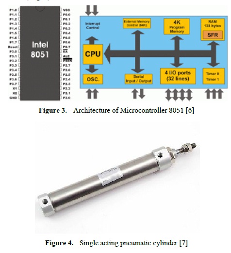
They are used to convert the pressure energy of air into mechanical work. They replace the human effort, by means of mechanical actuation. The cylinder used is a single acting cylinder (Fig.4) with spring return. Since air is the driving medium, they must be connected by means of polyurethane pipes to maintain the pressure required for the actuation. Two single acting cylinders are used, the former one to pull the brake cable and the latter extends the bumper horizontally. A sudden bust of air drives the piston of the cylinder along with actuators.
elay is an electrical switch that opens or closes under control of another electrical circuit. Relays can be programmed to control electronic circuits automatically. Relay acts as a switch between the electronic circuit and pneumatic assembly. When obstacle is detected microcontroller generates appropriate control signal to close the circuit of relay. The triggering distance is programmed in logic of microcontroller. The closing of the circuit allows the flow of current to the electro-mechanical switch.
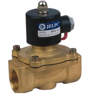
Solenoid valves are electromechanical switches that can be controlled with electronic circuit. They are used to control the flow of fluid and the device changes its state when current flows through its circuit. Solenoid valve (Fig.5) triggers pneumatic actuation on the completion of electric circuit. It hold the pressure of compressed air from the tank and lets the fluid to flow only on pre-crash condition. The unit consists of 2 solenoid valves that are triggered simultaneously. One of them is responsible for actuation of braking cylinder and the other is connected to cylinder of extendable bumper.
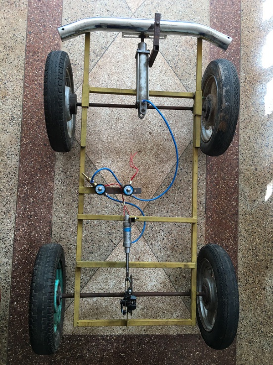
A 2cm × 2cm mild steel angle sections were cut and a frame of 92cm × 46cm was fabricated by welding. Four ball bearings were fixed to frame. A mild steel shaft was turned to a standard size which is placed as an axle. A standard tyre of 38cm diameter was fixed to the shaft. Provision is made to attach sensor, cylinders and all the components in the assembly.
Brakes are attached to the rear end of the vehicle. They are driven by pneumatic cylinder which operates on flow of compressed air. Assuming the weight of the whole setup not to exceed 30kgs, brakes from a 5 gear bicycle is selected for the purpose of braking. The bumpers that are installed are of extendable type. They have a stroke length of 80mm. Bumper is aimed for protecting the vehicle. On actuation of solenoid valves compressed air flows through the piston of pneumatic cylinder. The piston rod of the cylinder is welded to the midsection of the bumper.
Buzzer is an electric circuit that is connected to the microcontroller; it generates sound when current is passed through it. When programmed values are encountered by the microcontroller buzzer alarms the driver so that he can apply the brakes at right time. If the driver is quick enough to respond to brakes at right time collision can be avoided.
The completion of final model includes many more equipment namely transformers, connectors, hose collars, pipes compressed air tank and various other accessories. Arrangements have been made to place the sensor along with its board in front part of the vehicle.
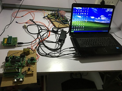
The Keil C51 compiler accommodates with AT89S52 microcontroller (Fig.6). The Keil chain tool has following tools located in its directory.
1. meu vision
2. C compiler C51
3. Assembler A51.
The weight of the whole setup is 25.2kg. The model as shown in Fig.7 successfully works in dummy traffic conditions. It can easily brake to complete still up to a speed of 10km/hr. The model can sense an obstacle up to 200cm and displays “NORMAL” on the LCD screen provided at safe distance. “FIRST ALERT” and “SECOND ALERT” is displayed on the screen at a safe braking distance of 125cm and 80cm respectively. An alert is given to the driver when these values are encountered in IC. When the clearance is at a close vicinity of 40cm automatic brakes are applied along with extension of bumper. Driver is alarmed simultaneously with these actuations. In various simulations conducted at different operating pressures, the model is found to have high degree of efficiency at a pressure range of 6-6.5bar. The sensor is effected by temperature, light and sound of the testing environment.
Ultrasonic sensor is well affected by the light incident on it, however model works better in night conditions. Use of brake cable allows intermittent braking; however the braking was not uniform in all conditions. Response time was very low, thus it provides better braking when compared to that of IR sensors. This mechanism can be used in all type of vehicles; an additional installation cost would provide a safer environment. Provisions can be made to disconnect accelerator pedal, to avoid confusion. Velocity and acceleration measuring devices could be integrated with ECU for automatic braking at higher speeds. Presence of an accumulator could possibly show a better response from the ECU. The system can be disconnected with a switch thus the ride will be comfortable even in heavy traffic.
[1] Olney R.D, "Collision Warning System Technology", Intelligent Transport Systems World Congress, Japan, November 1995.
[2] Katore S.R, Kadlag S.C, Mane P.V., "Automatic Braking with Pneumatic Bumper System", International Journal of Engineering, Volume3, Issue2, 2015.
[3] M. Magesh, Intelligent Braking System Using Microcontroller, Mechanical engineer in IFET College, Villupuram.
[4] http://www.micropik.com/PDF/HCSR04.pdf
[5] http://www.newagepublishers.com/samplechapter/002079.pdf
