


Published on Nov 30, 2023
Robotics is the new booming field, which will be of great use to society in the coming years. A Robot is defined as a reprogrammable, multifunctional manipulator which is designed to move material, parts, tools, or specialized devices through various programmed motions to perform a variety of tasks. A robotic arm is a mechanical device that travels specifically in a designed pattern, with sensors ensuring that all moments are exactly of the similar pattern. A robotic arm consists of several joints connected together by linkages. A robotic arm is usually programmable with similar functions to a human arm. Robotic arm can be used to perform a variety of tasks with great accuracy. The main purpose of using gestures is that it provides a more natural way of controlling and provides a rich and intuitive form of interaction with the robotic system. These days many types of wireless robots are being developed and are put to varied applications and uses. These robots are currently used in many fields of applications including office, military tasks, hospital operations, dangerous environment and agriculture.
Besides, for the activities that may be difficult, dangerous or harmful for humans, like picking up explosive chemicals or handling radioactive materials, taking readings from an active volcano, defusing bombs or in worst case scenario to pick and place the bomb somewhere for containment and for repeated pick and place action in industries and many more.
The integration of technologies like Electronics and Mechanical has emerged a new branch which is most famously called Mechatronics. Robotics is a part of Mechatronics. Robotics refers to duplication of human actions by machines. Robotics is a very vast field that has helped us make some wonderful machines that assist us in our daily lives. Typical industrial robots usually perform tasks that are difficult, dangerous and too complex. They lift heavy weights, and a lot of manual work such as welding can be done using robots. They can perform the same course of action in lesser time with more accuracy. Many people have used various technologies to build such kind of robotic arm with wired or wireless communication methodologies.
This proposed robotic arm is focused on developing a system that works wirelessly to recognize and control the robotic arm by using various methodologies such as hand gesture recognition technology, Zigbee wireless communication technology, MEMS-3 axis accelerometers, flex sensors etc. The combination of such latest technologies in a single platform has posed real challenge to design and develop. Hence, this work is undertaken to design and develop Zigbee based tele-operated multipurpose robotic arm with gesture recognition. Though the working of a robotic arm is very simplified, the implementation of this arm requires a good knowledge of Engineering Mechanics, Arduino platform, High end Atmega328 AVR RISC microcontroller, Electromechanical Devices mainly sensors, Mechanical Robotic Arm setup, Rover assembly and Embedded Systems as well.
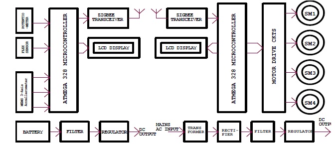
Typical industrial robots usually perform takes that are difficult, dangerous and too complex .they lift heavy weights, and a lot of manual work such as welding can be done using robots .They can perform the same course of action in lesser time with more accuracy zigbee wireless communication technology ,MEMS -3axis accelerometeres, flexsensor etc. The combination of such latest technologies in a single platform has posed real challenge to design and develop. This work is undertaken to design and develop teleoperated multipurpose robotic arm with gesure recoginition. Wireless communication technology etc. The name of our integrated project is tele-operated multipurpose robotic arm with hand gesture recognition .The main objective behind this project is to make a robotic arm that would imitate gesture of a human arm .As it is a zigbee based system, hence it has two important parts i.e a transmitter unit and a receiver unit.
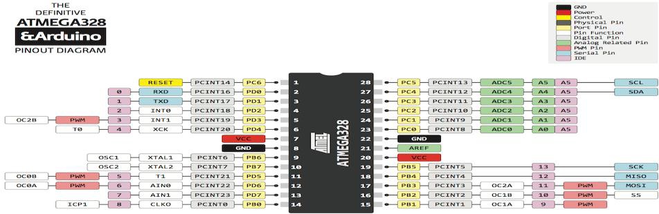
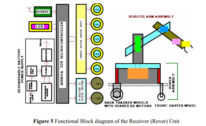
The microcontroller is the most important unit of this system. A microcontroller is a single chip computer that contains the processor (the cpu), non-volatile memory for the program (Rom or Flash), volatile memory for data input and output (ram), a clock and an i/o control unit, also called a "computer on a chip," billions of microcontroller units (MCUs) are embedded each year in a myriad of products from toys to appliances to automobiles. The ATmega328 is a single chip microcontroller created by Atmel and belongs to the megaAVR series. This Atmel’s 8-bit AVR RISC-based microcontroller combines 32 KB ISP flash memory with read-while-write capabilities. There are two Atmega 328 microcontrollers in this project, one in Haptic Glove Side Unit and another in Robotic Arm Side Unit. In the Haptic Glove Side Unit Atmega 328 microcontroller controls MEMS 3-axis accelerometers, flex sensors, potentiometer, LCD display and Zigbee transceiver and the other Atmega 328 microcontroller in Robotic Arm Side Unit controls Zigbee transceiver, LCD display and Servo Motors etc. in this project.
MEMS stands for Micro Electro Mechanical Sensor. MEMS accelerometers are one of the simplest but also most applicable micro-electromechanical systems. ADXL335 is a MEMS based accelerometer that measures acceleration forces. These forces may be static, like the constant force of gravity pulling at your feet, or they could be dynamic - caused by moving or vibrating the accelerometer. The 3-axis accelerometer outputs three analog values corresponding to the X, Y & Z proportional to the tilt direction coordinates. By sensing the amount of dynamic acceleration, we can analyze the way the device is moving. These voltages are fed to ADC part of the microcontroller. The microcontroller routinely checks the outputs of the accelerometer and obtains the values tilt in each direction. The advantage of the accelerometer was that the values do not change unless there is a change in position.
- Flex is basically a strip of carbon material having metal pads and are basically analog resistors, within a thin flexible substrate that change in resistance depending on the amount of bend on the sensor. As the sensor is flexed, the resistance across the sensor increases. They work as variable analog voltage dividers. They convert the change in bend to electrical resistance the more the bend, the more the resistance value. They are usually in the form of a thin strip from 1”-5” long that vary in resistance.
A potentiometer, informally a pot, is a three-terminal resistor with a sliding or rotating contact that forms an adjustable voltage divider. Potentiometers consist of a resistive element, a sliding contact (wiper) that moves along the element, making electrical contact with one part of it. Potentiometers operated by a mechanism can be used as position transducers. There is a direct relationship between slider position and resistance. Potentiometers are commonly used to control electrical devices such as volume controls on audio equipment or in a joystick etc. In this project, we have used two potentiometers, one for sensing ankle joint and the other for sensing shoulder joint position.
Zigbee is a specification for a suite of high level wireless communication protocols using small, low-power digital radios based on an ieee 802.15.4 for personal area networks. Zigbee is targeted at Radio Frequency (RF) applications.The zigbee, also known as xbee technology allows these devices to act as routers or end devices. Zigbee Transceiver Interfaces and Level Converter The microcontrollers have two pins that are used for transferring and receiving data serially. These two pins are called TXD and RXD and these pins are TTL compatible. The zigbee transceivers work on RS-232 standard. The RS-232 standard is not compatible to TTL, therefore, it requires a line driver such as the MAX-232 chip to convert RS-232 voltage levels to TTL levels, and vice versa.
Servo motors are a type of electromechanical actuators that do not rotate continuously like DC/AC or stepper motors; rather, they are used to position and hold some object. They are used where continuous rotation is not required so they are not used to drive wheels (unless a servo is modified). In contrast they are used where something is needed to move to particular position and then stopped and hold there.
The system has a LCD display module for displaying various prompts and status information of the system and the positions of various servos. A 2-line, 16 character type LCD display module is used.
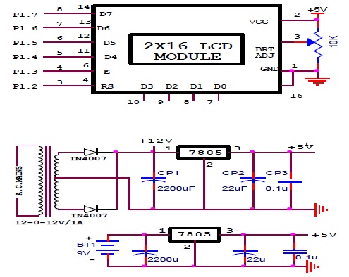
Power supply section has to provide a regulated D.C supply to all sections of the system. As already mentioned, the Haptic Glove Side Unit is designed work on compact 9V battery and Robotic Arm Side Unit can derive power from rechargeable batteries or AC mains derived DC supply. In case it derives power from AC mains and coverts it into DC power at low voltages. It consists of a step-down transformer, rectifiers, filters and regulators.
The number of joints determines the degrees-offreedom (DOF) of the manipulator or regulator. Typically, a manipulator should possess at least six independent DOF: three for positioning and three for orientation. With fewer than six DOF the arm cannot reach every point in its work environment with arbitrary orientation. In certain applications such as reaching around or behind obstacles require more than six DOF. The difficulty of controlling a manipulator increases rapidly with the number of links. A manipulator having more than six links is referred to as a kinematically redundant manipulator. The workspace of a manipulator is the total volume swept out by the end-elector as the manipulator executes all possible motions. The workspace is constrained by the geometry of the manipulator as well as mechanical constraints on the joints. For example, a revolute joint may be limited to less than a full 360◦ of motion. The workspace is often broken down into a reachable workspace and a dextrous workspace. The reachable workspace is the entire set of points reachable by the manipulator, whereas the dextrous workspace consists of those points that the manipulator can reach with an arbitrary orientation of the end-elector. Obviously the dextrous workspace is a subset of the reachable workspace.
A Robotic Arm is a robot manipulator, usually programmable, with similar functions to a human arm. The links of such a manipulator are connected by joints allowing either rotational motion (such as in an articulated robot) or translational (linear) displacement. The links of the manipulator can be considered to form a kinematics chain. The end of the manipulator is called the end effectors and it is analogous to the human hand. The end effectors can be designed to perform any desired task such as welding, gripping, spinning etc., depending on the application. The robot arms can be autonomous or controlled manually and can be used to perform a variety of tasks with great accuracy. The robotic arm can be fixed or mobile (i.e. wheeled) and can be designed for industrial or home applications. The following fig shows general structure of robotic ARM.
A small object of low weight is placed near the robotic arm at a distance within the approach of arm. The system is made on. The operator stands at a distance from the robot and moves the finger/hand up, down, left or right. The robotic arm follows the direction. The arm is brought over the object and then lowered. The gripper is fully opened to pick up the object. The robotic arm then is moved up and rotated to another desired position, then lowered. When the arm reaches the floor, the gripper is given a command to release the object, which places it at the desired location. This way the robotic arm can be operated and controlled in any manner as deemed necessary by the operator from a distance, usually up to 200 meters.
The system operation can be performed by the following sequence of steps.
Switch ON the hand held remote control unit and position the rover platform near to the object.
A small object of low weight is placed near the robotic arm at a distance within the approach of arm.
There are three sensors to create movement in the robotic arm such as accelerometer, flex sensor (gesture glove) and some potentiometers.
The operator stands at a distance from the robot and moves the finger/hand up, down, left or right.
The arm is brought over the object and then lowered.
The gripper is fully opened to pick up the object.
The robotic arm then is moved up and rotated to another desired position, then lowered.
When the arm reaches the ground floor, the grabber is given a command to release the object, which places it at the desired location.
This way the robotic arm can be operated and controlled in any manner as deemed necessary by the operator from a distance, usually up to 100 meters wirelessly.
This system is wirelessly controllable gesture operated pick and place output robotic arm with hand gesture. The zigbee transceiver module is working on the ISM band frequency of 2.4 GHz and has a range of 50-80 meters. A gripper will allow the movements of the palm and allow picking and placing of objects. The system was implemented by first designing the hardware and later the software. Hardware design began by designing individual circuits and their testing. The Printed Circuit Board (PCB) was designed using Protel PCB making software. PCBs are fabricated by the manual process using screen printing and chemical (FeCl) etching technique. After the holes are drilled, the mounting of components and soldering was carried out. This system has functioned reliably and the trials have been carried out with acceptable results. It was rigorously tested for its proper operation and reliability. From observations, during trials, it clear that its movement is precise, accurate This prototype device is easy to use and user friendly. In fact, the device, despite the several functionalities, has acceptable dimensions. This robotic arm control is expected to overcome the problem such as placing or picking object that away from the user, pick and place hazardous object in a very fast and easy manner.
As we implemented a hand in our project i.e is only a part of human hand ,futher we can implement full fingers with some number of flex sensor and small servo motors. and even futher it can be implemented to full human body to relicate the operation in the medical surgery. industrial automation equipment and goods carrier ,tour guide in museum ,deliver the mail in office building, delivers medication in the hospital, can be used in place of crane in various lifting and carriage applications
The objectives of this work has been achieved which was developing the hardware and software for an accelerometer and flex sensor based wirelessly controlled robotic arm which wirelessly moves robot arm and works according to your hand gesture. The robotic arm has been developed successfully as the movement of the robot can be controlled precisely. Microcontroller programming is done to drive the serve motor for wireless control of the robotic arm by employing zigbee wireless application protocol. The zigbee transceiver module is working on the ISM band frequency of 2.4 GHz and has a range of 50-80 meters. A gripper will allow the movements of the palm and allow picking and placing of objects. This system has functioned reliably and the trials have been carried out with acceptable results. It was rigorously tested for its proper operation and reliability. From observations, during trials, it was found that its movement is precise, accurate. This prototype device is easy to use and user friendly. In fact, the device, despite having several functionalities, has acceptable dimensions. This robotic arm control is expected to overcome the problem such as placing or picking object that away from the user, pick and place hazardous object in a very fast and easy manner.
[1] Abidhusain Syed., Zamrrud Taj H., Agasbal., Timmannagouday Melligeri and Bheemesh Gudur “Flex Sensor Based Robotic Arm Controller Using Microcontroller”, Journal of Software Engineering and Applications, Vo-5, No-2, pp 364-366, 2012.
[2] Shamsheer Verma “Hand Gestures Remote Controlled Robotic ARM”, International Journal of Advance in Electronic and Electric Engineering, Vol-3, Number-5, pp 601-606, 2013.
[3] Shivani., Shagun Gaur., Paresh Khaneja., Rashmi Sharma., Simranpreet Kaur and Mehakpreet Kaur “Efficient Approach for Designing Gesture Controlled Robotic Arm”, International Journal of Control and Automation, Vol-6, No-6, pp 55-64, 2015.
[4] Vivek Bhojak., Girish Kumar Solanki and Sonu Daultani “Gesture Controlled Mobile Robotic Arm Using Accelerometer”, International Journal of Innovative Research in Science, Engineering and Technology, Vol-4, issue-6, pp 4538-4554 , 2015.
