


Published on Nov 30, 2023
When the voltage of a car battery corrupts, it cannot be able to ignite the car engine. Therefore, a bi-directional power converter stage is developed. It can extract the remaining energy stored in the car battery and store it into a bank of supercapacitor as an alternative power source. Once the voltage of the car battery falls below the rated voltage and the car engine need to be started, the bank of supercapacitor can act as an alternative power source to start the car engine. This power stage consists of a boost power stage and a buck power stage. They are combined together such that bi-directional energy flow is allowed. When a voltage corruption of the car battery is detected, the bank of supercapacitor is charged up from the week battery by the boost power stage and its voltage is regulated at 36V. Under this condition, if the car engine needs to be ignited, the topology of the power stage will turn to the buck mode. The current needed in the starting process of the car engine is then provided by the supercapacitor as the input voltage source and the output voltage supplied to the car engine is regulated at 12V. This power stage can be treated as back up facilities for car engine igniting.
Since Benjamin Franklin tried to know the lightning (electricity) in 17th century [1], the development of human went up with a leap until now. People start to use this type of energy to work efficiently. The electricity is a main energy source in our life. With the rapid development of power electronic technology, many of the power converters were developed. Different types of power conversion became available such as AC-AC, AC-DC, DC-AC and DC-DC. In 1970s’, the three basic topologies which convert DC at one level to another level were developed in the Power Electronics Group of Caltech in California, USA: boost, buck and buck-boost .
The boost circuit steps up the DC input voltage; the buck circuit steps down the DC input voltage and the buck-boost circuit is either stepping up or stepping down the output voltage but its polarity of the output voltage is opposite to its input. Nowadays, this technology of these three power circuit are still applied in our life. Many designs are based on these three topologies as a building block and are modified to develop other new applications. For example, the boost circuit and buck circuit are combined together, the buck circuit is modified to from a flyback converter. In this report, the boost circuit and buck circuit will be combined together. The principles of this circuit will be discussed and the experimental result will be showed
In general, the knowledge of people accumulates for our living; the standard of living is also advanced. The area of the activities of people increases so much. Therefore, people need a vehicle to travel places they want. Each car contains a battery which provides energy to start up the car-engine. However, when the car battery is exhausted and its voltage is dipped, the car engine cannot be ignited. In traditional, a booster cable (jumper cable) is used to connect a good battery of a car to the dipped battery of another so at to restore the dipped battery. Figure 1 shows the connection of the dipped and good battery. In this time, the car can ignite again and it should be sent to repairing center. On the other hand, if a good battery from other car is not available, the cat should be towed to car-maintenance center for repairing.
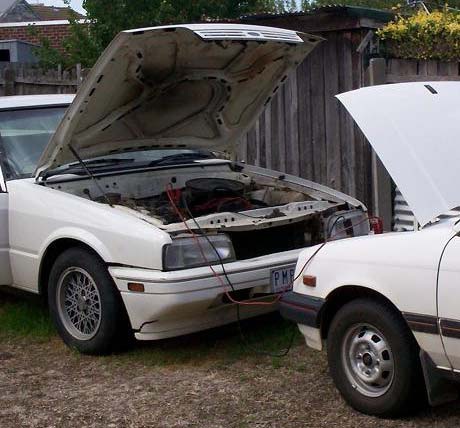
Besides, no other alternative system is installed in the car which can make it move. The car battery is still having the energy but the voltage is not high enough to ignite the car.
The purpose of this project is to extract the remaining energy from the dipped car battery and store it to an energy storage device. Therefore, the following task should be done:
�� To investigate which components are suitable for used as an energy storage device for demand of high energy density.
�� To investigate the circuit of the car especially on the car starter and engine.
�� To develop whatever power circuits are used for bi-directional power circuit of which the efficiency should be high.
�� To develop a control circuit or board for controlling the power circuit.
�� A experimental prototype is built for investigating the operation and efficiency of the power circuit.
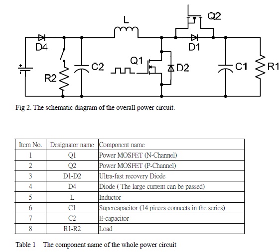
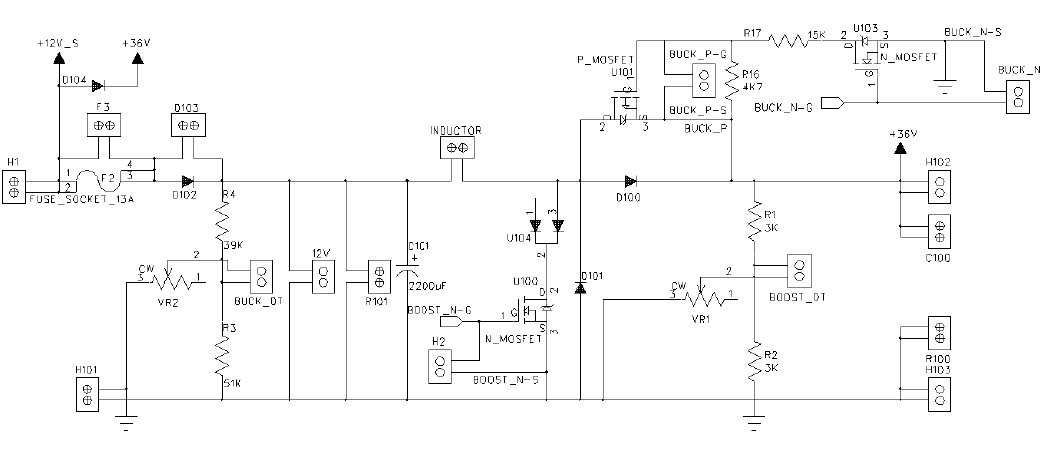
Since the power circuit is a bi-directional power-handling stage, it consists of a boost converter stage and a buck converter stage which are combined together. The diode D4 is operated in forward bias mode because it will let the current pass through the D4 while the boost converter is operating. The diode D4 is operating in the reversed bias when the buck mode is running; it prevents the current from going back to the source. In each of the boost and buck mode of the power circuit shown in figure 2, they can operate in continuous mode and discontinuous mode. Since the design is focused on the continuous mode, the following discussion is confined in continuous of operation.
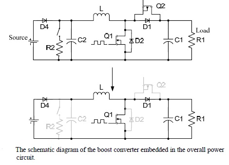
From figure 3, the battery is the input voltage source and resistor R1 is the load. The power circuit is of boost type which is operated in continuous-conduction mode [6]. The name of the boost converter implies that the output voltage of capacitor C1 is always greater than the input voltage.
Why the supercapacitor is selected to be used in the power circuit? It is because the supercapacitor has a property of higher energy density compared with general-purpose capacitor. Also, its equivalent series resistance (ESR) is very low. For example, The ESR of a supercapacitor with capacitance 650F is 1.15mΩ [10]. It can sustain high charging and discharging current. On the other hand, its recharging cycle is over one million times [10]. Its lifetime is longer than the re-chargeable battery. The target output voltage is 36V, however, a piece of supercapacitor can be only charged to 2.7V. The 14 pieces of the supercapacitors could be connected in series. In figure 11, the 14 pieces of the supercapacitors from a bank of the supercapacitor.
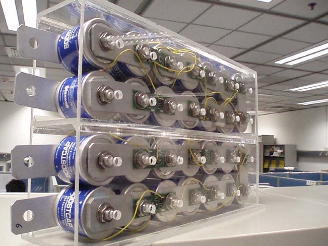
Although a series of the supercapacitors can be connected together, the voltage of each supercapacitor may not be the same. If one of supercapacitors is over voltage, it may explode. Thus, they need a balance circuit which balances the voltage of each capacitor in the capacitor-bank
Figure gives an overview of the control circuit. The gate signal controlling the power switch in both of buck and boost mode is provided by the PWM controller. The function of relay circuit is to select the modes of operation (i.e. the buck and boost mode) by changing the connection of the gate signal and output voltage sensing signal to the boost or buck stage. Also, it can provide the indication of the fully charged status of the bank of supercapacitors and detect the dip of the battery voltage when the voltage of battery is lower than 9V (by the igniting detector) during the ignition process of the car.
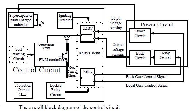
The first part of the control circuit is the protection circuit. It prevents the control circuit from destroying by short circuit. In this control board, if all function is operating, the current should not be greater than 300mA. Therefore, the current rating the fuse is designed at 500mA. Although the input current has a little fluctuation, it will not be burned and it can protect the control board.
Recently, the idea of the environment protection is considered frequently. The hybrid vehicle is better than a conventional vehicle since it can reduce the wasted energy. The investigated power circuit in this project is the hybrid energy storage system (HESS). It can be installed in vehicles. Thus, it can mix fuel and HESS for the car.
Also, it can act as a support system in uninterruptible power supply (UPS). Since the circuit design in this project is bi-directional, it can use another control circuit to release the energy to source when there is energy shortage occur at the source.
In this project, an experimental prototype of proposed bi-directional power circuit is built and tested. It is observed that the supercapacitors can be charged up to the required voltage level in the boost mode of operation. The time taken for the charging process is about 20 minutes. The operation of the boost mode is then switched to the buck mode with a delay time of 300ms. It is also observed that the supercapacitors can successfully deliver the energy to the load in the buck mode operation. Based on the experimental result, it can be shown that the functions of the proposed system are realized. Therefore, the proposed system can be used in an energy backup system due to high energy density of the supercapacitor. It is very useful for the future since the HESS will be used more in future.
1) http://code-electrical.com/historyofelectricity.html
2) http://www.steve-w.dircon.co.uk/fleadh/mphil/history.htm
3) http://www.answers.com/topic/booster-cable
4) http://www.answers.com/topic/jump-starting-jpg
5) http://en.wikipedia.org/wiki/Boost_converter
6) Power Electronics: Converters, Applications, And Design, 3rd Edition, Mahan, Undeland, Robbins
