


Published on Nov 30, 2023
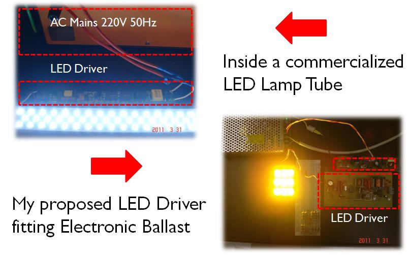
LED lamp tubes are becoming more and more popular in recent light fixture market, especially fluorescent lamp tube replacement market. To replace a LED lamp tube directly with fluorescent lamp tube, a special design for LED driver compatible with the supply sources output by electronic ballast needs to be proposed. In this project, under the guidance of Professor Henry Chung and the help of his research group in Power Lab of CityU, a design of LED driver which can be embedded in LED lamp tube that can operate with electronic ballasts without rewiring the existing circuitry inside the fluorescent lamp holder is presented. Another feature of this LED driver is the function of dimming control. The kernel technology of this driver design to achieve the power conversion is the adjustment of the input impedance of AC-to-DC converter. Through this adjustment, the active and reactive power drawn from the electronic ballast to the LED lamp can be controlled.
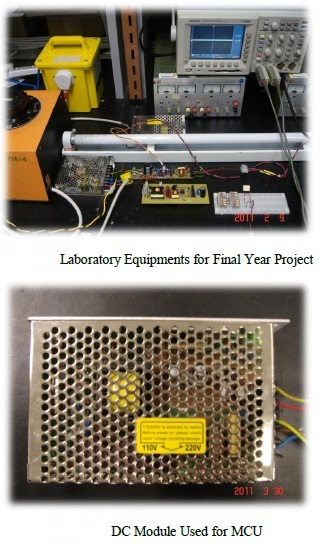
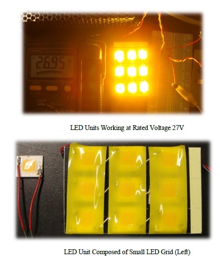
The concept of this retrofit design allows convenient replacement of fluorescent lamps with LED lamp tubes without removal or replacement of existing electronic ballasts. Once the prototype is commercialized and finally becomes real product, the market potential will be huge, since customers who could afford this kind of retrofit LED lamp must have used electronic ballasts before. A 20W retrofit LED lamp prototype is built, and the performance of it is evaluated in this project.
Fluorescent lamp tube has been widely used as light equipment, due to its advantages of providing longer lifespan and less power consumption than an incandescent light does. However, it might not be as energy-efficient as LED lamps today. On contrary, the leakage of mercury from wasted fluorescent light has even become another source of pollution to the environment. Therefore, the idea of replacing the fluorescent tube with LED was getting more and more popular. Should this idea be realized, it will do help human society to save huge amounts of energy and solve many environmental problems. However, realizing this feasibility in practice is frustrated by a number of difficulties. Firstly, there will be considerable labor costs involved in the installation, because people need to open the light fixture to disassemble the existing ballast, either it be an electronic one, or a magnetic one. Secondly, people might just throw away the removed ballasts. Clearly, it is not a desired solution for fluorescent lamp replacement, because of the extra costs paid and lack of recycle scheme of ballasts.
Instead of removing the existing electronic ballast for installation of LED lamp tubes, my research presents a LED driver embedded in the naked LED lamp to allow a direct replacement of fluorescent lamps. The proposed LED driver has a value-added function, which is dimming control. The new type of LED lamp tube is called ―retrofit design of LED lamp‖. Clearly, this solution outperforms the current method of fluorescent lamp replacement. This project is aimed at designing the circuitries of a LED driver which could be geared on electronic ballast for fluorescent lamp tubes. In order to drive the LED lamp in DC mode, basic knowledge of power electronics, including AC-to-DC conversion, DC-to-AC conversion (inverter) and PWM control, need to be used.
The design procedures started from an investigation on the performance of electronic ballast, and continued with a simulation process by trial and error of the circuitries of half-bridge rectified, and finally ended with the construction of the mathematical model of the circuit system and the solutions of the parameters. The final design was consolidated on computer simulation and verified by experimental result. The software used for computer simulation in this project is PSim, which is recommended by Professor Henry Chung and PhD candidates.
This software is actually very popular in the field of power electronics and electrical-mechanical control. PSim is capable of nearly all the circuit simulation in power electronics, with a user-friendly interface, fast-computation speed, high resolution and accuracy. In some other procedures and discussions of this report, computer aid of Microsoft Mathematics was used in the active/reactive power analysis.
To study the basic knowledge of LED lamps and different categories of LED drivers
To study the working principles of electronic ballast
To investigate on the methods of dimming control
To use the principle of AC power engineering for the driver design
To compare different modes of LED driver and draw a conclusion
LED technology is an obvious area that we can achieve energy savings as well as economic benefits in the next decade. Currently, LED technologies are successful in decorative, display, signaling and signage sectors, but not so successful in general public lighting sector. Compared with the traditional fluorescent lamps invented half a century ago, LEDs tend to have longer life expectancy and higher resistant to vibration failure. They also consume less power than all light equipment nowadays. Moreover, they contain no toxic elements, such as mercury, and emit no ultra-violet light, which is harmful for human health. However, The high cost (usually 10 times that of fluorescent tubes) of all kinds LED lamps is one factor that deters general customers from using LED lamps, the incompatibility of electricity infrastructures, including the AC electricity supply and the use of lamp ballast is another important issue that resists the mass application of LED lamps.
LED lamps have a promising future. All research interests about LED as daily lighting sources saw an amazing development in the past five years, including electrical interfaces (drivers, power management), mechanical interface (fixture design, housing and geometry of LED grids), thermal interface (heat sink) and photometric interface (material science & engineering). It is estimated that all key elements for research in this research area will be improved steadily until the year 2015, when all standards of LED as lighting equipments finally become mature and strictly regulated.
As estimated by China’s Bureau of Energy, 400 millions of new fluorescent lamps were purchased in domestic market of China, and around 1 billion fluorescent lamps were used. If it is assumed that on average 4 hours of running time per lamp and the power rating of LED lamp is 25 Watts, then on average the power consumed is 0.1 KWh per day. With a rough calculation, 30 billion KWh of electricity will be consumed per year. If LED lamp is assumed to save half of the power consumed by fluorescent lamp, only 15 billion KWh of electricity will be used. If we could add dimming control to LED lamps and we assume that around 10% more electricity could be saved by it, 1.5 billion KWh more electricity will be saved again. This is a considerable number, because if 0.7RMB/KWh, around 1 billion RMB (= 153million US$) will be saved. We could reinvest this amount of money to investigate on more efficient lighting equipments.
In the market, LED lamp tubes and other LED light fixtures must be equipped with LED drivers to function. Since LED lamp requires AC-to-DC conversion, (See section 2.4 for Rectifier) an important electrical component plays a key role, which is the capacitor used for smoothing the voltage. Normally electrolytic capacitor, which has lower cost, is massively used in LED drivers. The figure (Figure 1) below displays four typical models of LED drivers.
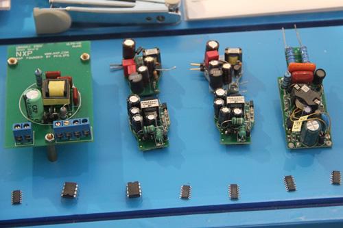
It could be seen that components like transformers, capacitors, MOSFETs and diodes, which are necessary components for rectifiers, are used in these drivers. However, it is estimated that the electrolytic capacitor has only a lifespan of several thousand hours. Therefore, the lifespan of the whole LED lamp (with driver) has a bottleneck in terms of this electrolytic capacitor. The reason why electrolytic capacitors could pose a serious degradation to the lifespan of LED lamp is because of the vaporization of the electrolytic liquid inside due to the temperature rise in the circuit. Without an efficient and long-life capacitor to achieve the smoothing effect of AC-to-DC conversion, advantage of LED lamp’s longevity of working hours could not be revealed.
Successful LED drivers could facilitate the energy-saving mission, since the power consumption of the LED lamp is generally lower than that of the fluorescent lamp. In addition, the proposed retrofit design of LED lamp could provide dimming function with users, which means more energy-saving capacity.
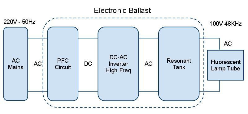
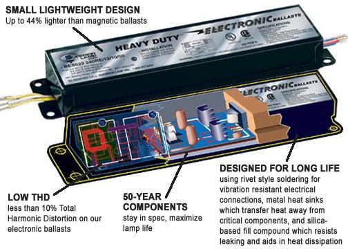
Fluorescent lamp converts electrical power into useful light more efficiently than an incandescent lamp. Lower energy cost typically offsets the higher initial cost of the lamp. In the lamp fixture holding fluorescent lamp tubes, a kind of power conversion device, ballast, needs to be added in order to regulate the current flowing through the lamp. Electronic ballast, which functions at high-frequency to drive the fluorescent lamp, has been widely used with fluorescent lighting systems for over 30 years. It tends to be more energy efficient and runs more quietly than traditional magnetic ballasts. Compared with traditional magnetic ballast, electronic ballast can reduce the flickering effects of the lamp and hence creates a comfortable light output to human eyes.
Higher power efficiency
High frequency mode, no obvious flickering effect
Less noisy, no buzzing sound
Easy to achieve dimming control
Extending the lifespan of fluorescent lamp
Easy for implementation of PFC circuit
High input power factor (pf)
Low input current total harmonic distortion (THD)
Good lamp current crest factor (CF) (see Section 2.9 – 2.10)
Lighter weight and smaller size
However, there are some disadvantages of using electronic ballasts. Firstly, electronic ballast tends to be more reliable than magnetic ballast, but its burn-out rate are on average higher than its magnetic counterpart. Secondly, once a lamp ballast has burned out, the only way to save is to replace it by a new one. Thirdly, since electronic ballasts work at very high frequencies (20 – 60 KHz), they can create radio frequency noise and electromagnetic interferences to power lines and indoor ambience. However, these issues belong to general education, and will not be discussed in this report.
Power Factor pf is an important gauge in AC power system. Please see section 2.6 AC Power for explanations in detail. The cause of low pf is due to the property of rectification process explained in Section 2.5. They ―polluted‖ the public electricity transmission system extraordinarily, but they are still massively used, because of their simplicity in structure and low cost. Without PFC circuit, a single device connected to the AC mains might not be revealed clearly. But if millions of such devices that have no PFC regulation, the highfrequency harmonics contained in the pulsating current might ―pollute‖ the whole electricity transmission system in a large extent. Excessive current harmonic components might cause more power consumption and heat for electrical engines and generators with contains coils. It might also break down the electronic ballast. When it comes to the worst case, it might also lead to burnt-down and fire, and huge amounts of economic losses. Therefore, from perspectives of protecting the electrical system as well as protecting human safety, current harmonics must be reduced as much as possible.
Problems of having no PFC circuit:
Sharp and high current pulse, around 10-20 times of current in steady-state
Narrow conduction angle, THD (Please see section 2.8) will even reach 100%
In this section, Power Factor Correction (PFC) circuits that are typically used in driving circuits will be introduced. The basic working principle of PFC circuit is to force the pulsating current to follow the phase pattern of voltage, by using a control circuit. Achieving a sinusoidal current with a phase synchronization of sinusoidal voltage, PFC circuit could be seen as a purely resistive component in the circuit. Figure 9 is a circuit schematic of Active PFC circuit.
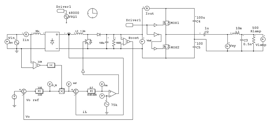
For analysis of PFC circuit, please see Section 4 for simulation results. Since there are embedded PFC implementation in the commercialized electronic ballast, PFC is not considered in the performance analysis of the circuit.
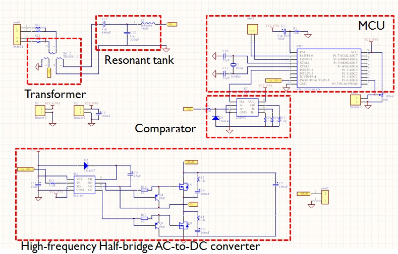
In this final year project, a design of LED driver used for retrofit LED lamp that can function with the output of electronic ballasts for fluorescent lamps has been presented. The driver is useful for the popular LED replacements for fluorescent lamp market. Background knowledge about Power Electronics and AC Power were discussed. Key tools for circuit design and analysis were reiterated. The experimental results match the theoretical prediction of the unique active/reactive power dimming control method. However, there are some limitations for this method, and the limitations were discussed. A further design of LED driver that can be connected to the output of lamp ballast (highfrequency electronic one or low-frequency magnetic one) or AC mains with dimming control function needs to be studied. The new driver uses nearly the same principles of the driver studied in this report. It will be a power converter with controllable input impedance for the ballast or ac mains, and with its output to be controlled for dc-powered LED. The proposed universal LED driver will be operated as an AC-to-DC resonant converter with controllable impedance that are both resistive and reactive (i.e. having both real and imaginary part), so that the active power and reactive power delivered to the LED can be adjusted, which is the dimming control function.
[1]. A Driving Technology for Retrofit LED Lamp for Fluorescent Lighting Fixtures With Electronic Ballasts, Nan Chen, Student Member, IEEE and Henry Shu-Hung Chung, Senior Member, IEEE
[2]. A Dimming Module for Controlling Power Supplying to a Fluorescent Lamp Ballasted by a Nondimmable Electronic Ballast, Nan Chen, Student Member, IEEE, and Henry Shu-hung Chung, Senior Member, IEEE
[3]. Multi-Year Program Plan FY 09 – FY 15, Solid State Lighting Research and Development, Prepared by Navigant Consulting, Inc., Radcliffe Advisors, Inc. and SSLS Inc.
[4]. A Very Simple Control Strategy for Power Factor Correctors Driving High-Brightness Light-Emitting Diodes, J. Sebastian, D.G. Lamar etc.
[5]. Power Driver Topologies and Control Schemes for LEDs, Heinz van der Broeckl, Georg Sauerlander etc.
