

Updated on May 29, 2026
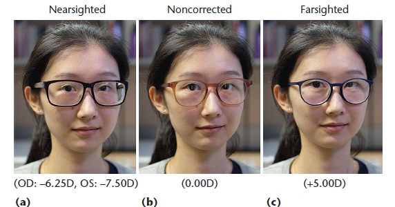
Vision-correcting eyeglasses have improved the lives of millions of people. Eyeglasses significantly affect the wearer’s appearance, and the selection of new pairs of eyeglasses is largely based on how the glasses look when wearers try them on. However, an often overlooked fact is that corrective lenses introduce distortion caused by the refraction effect. As Figure 1 illustrates, the eyes of a person wearing corrective lenses for nearsightedness appear smaller compared with wearing nonprescription lenses, whereas the eyes of a person wearing lenses for farsightedness appear larger. The traditional process of trying on and picking new eyeglasses frames in a brick-andmortar shop has a significant shortcoming: eyeglasses on the display are equipped with demo lenses that have zero corrective power, and thus refraction does not deform the eyes.
Thus, customers cannot see what they will actually look like until their custom prescription lenses are installed in the frames and the sale is final. Their appearance will differ from the in-store trial, which may cause disappointment and buyer’s remorse, especially for customers with strong eyeglasses prescriptions. A similar issue occurs with online stores, which allow customer to virtually try-on eyeglasses frames by overlaying them onto an input image. The online systems still do not adjust the image for the refraction effect.
We present a system for virtually trying on prescription eyeglasses. Our system acts as a virtual mirror, allowing users to try on a variety of eyeglasses with corrective lenses based on their prescription (see Figure 2). We use an image sequence of the user without eyeglasses as input, along with the user’s eyeglasses prescription and a 3D model of the desired eyeglasses frame. Our system generates a 3D representation of the corrective lenses mounted into the eyeglasses frame and modifies the video sequence to virtually insert the eyeglasses using image-based rendering. This approach simulates the distortion introduced by the prescription lenses and gives users a better idea of how they would look when wearing the new pair of eyeglasses.
To the best of our knowledge, the proposed virtual try-on system for prescription eyeglasses is the first to account for refraction effects. (See the “Related Work in Virtual Try-On Applications” sidebar for more details.) Our system was inspired by the traditional eyeglasses manufacturing pipeline followed by opticians. We generate a 3D representation of the corrective lenses that fit the user’s eyeglasses prescription and the chosen eyeglasses frame. Then, an image-based rendering technique virtually inserts prescription eyeglasses into the input video, while taking into account the effects of refraction, reflection, and shading. The findings from our user study highlight the importance of refraction and reflection in the perceived realism of virtual try-on results.
The virtual try-on system we developed inserts prescription eyeglasses onto the user’s face and simulates important changes to the appearance due to refraction, reflection, or shadows cast on the face. The system uses the following three elements as input:
An image sequence of the user without eyeglasses is captured with a color camera.
An eyeglasses prescription, usually provided by an optometrist, specifies the value of all parameters necessary to correct blurred vision due to refractive errors, including myopia, hyperopia, presbyopia, and astigmatism. Table 1 shows a typical eyeglasses prescription.
The user chooses the desired eyeglasses frame. The eyeglasses geometry is typically accessible from online stores, which scan and digitize the eyeglasses frames.
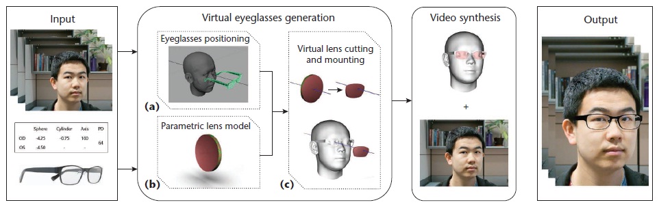
For this work, we purchased 3D models for six different commercially available eyeglasses frames from TurboSquid (www.turbosquid.com/3d-model/ glasses/). Figure 3 gives an overview of our approach’s pipeline, which consists of two main stages: virtual eyeglasses generation and video synthesis. In the first stage, we generate a 3D representation of the prescription eyeglasses (the frame and corrective lenses), with an appropriate position relative to the user’s face geometry. Inspired by the traditional eyeglasses manufacturing pipeline, this virtual eyeglasses generation stage has three steps:
1. Positioning the eyeglasses on the user’s face. After an initial manual positioning step for the first frame, we use face tracking to automatically align the eyeglasses with the user’s face in the following frames.
2. Creating a parametric lens model. Based on the user’s prescription and desired lens properties, this model describes the geometry of the uncut lens before mounting.
3. Cutting and mounting the lens. We trim the lens geometry according to the shape of the eyeglasses frame and insert the virtual lenses into the eyeglasses frame.
To begin our discussion, we briefly describe the traditional eyeglasses manufacturing process, before introducing our proposed system. Once the customer has chosen an eyeglasses frame for purchase, the optician measures the pupillary distance (PD), which is the horizontal distance between the left and right pupils. This can be done by marking the position of the pupils on the demo lenses, while the customer has the glasses on. This step is essential to ensuring that the prescription lenses will be appropriately positioned with respect to the eyes.
The next step is to choose lens blanks based on the strength of the correction needed and desired lens properties (for example, lens material). Lens blanks are circular, uncut lenses that are usually stocked by the lens manufacturers, with a variety of front surface curvatures. If necessary, the back surface of the lens is ground and polished to produce a lens according to the desired prescription. The eyeglasses frame is then inserted into a dedicated tracing machine in order to measure its inner contours, which will be used to cut the lens blanks to the appropriate shapes. Each lens blank is placed into an instrument to locate and mark its optical center; these points will be positioned in front of the customer’s pupils to ensure optimal vision. Finally, an edging machine is used to trim the lens blanks into the proper lens shapes, according to the previously measured contours. The cut lenses are then inserted into the eyeglasses frame. We create virtual eyeglasses with a similar process. First, we place the eyeglasses frame appropriately onto the user’s face geometry. Next, we build a parametric model representing the geometry of each lens according to the user’s eyeglasses prescription. Finally, lenses are cut and mounted into the eyeglasses frame.
Similar to the optician pipeline, we first place the eyeglasses frame with respect to the user’s face geometry. We obtain the geometry and pose of the user’s face for each frame by tracking the face using the Faceshift software1 and a Primesense Carmine 1.09 RGBD sensor. Calibration between the RGBD sensor and the color camera, which is used to capture the user’s input image sequence, is performed with a camera calibration toolbox.2 The camera’s intrinsic and extrinsic parameters let us align the face geometry with the input color images. Next, we manually position the eyeglasses onto the face mesh for the first frame.
For all the examples we tested, this process took less than 5 minutes on average. A fully automatic option would use affine transformation computed based on preselected feature points on face and eyeglasses 3D model3 or a physics-driven technique.4 After the initial manual positioning of the eyeglasses for the first frame, we track the head pose to automatically align the eyeglasses with the user’s face in the subsequent frames. This is achieved by calculating the relative pose change in each frame.
Given the user’s eyeglasses prescription, we generate the 3D lens geometry based on a parametric model so that the optical power of the virtual lens corresponds to the user’s prescription. A lens is a 3D transparent and closed object. It consists of two main surfaces: a front surface and a back surface. The lens thickness is defined as the distance between front and back surface along its optical axis. Physical lenses are made of a transparent material with a certain refraction index, which affects lens thickness, weight, and optical properties.
Optical power refers to a lens’ ability to bend light rays, as specified by the eyeglasses prescription. The front and back surface curves determine the lens’ optical power. Spherical lenses are rotationally symmetric, and their front and back surfaces have a constant curvature. In contrast, the surface curvature of toroidal lenses, which are used to correct astigmatism, varies with the direction; it is usually defined along two orthogonal directions called the axis meridian and power meridian. Modern lenses generally take a meniscus shape, with convex front curves and concave back curves.
The optical power P of a lens measured in diopters is given by
P = F + B + (t/h) * F2,
where F and B are the front and back power in diopters, t is the lens center thickness in meters, and η is the index of refraction. The focal power P is specified by the user in the form of an eyeglasses prescription.
Inspired by real lens-cutting machines, we detect the 2D inner contour of the eyeglasses frame from a front-facing view and extrude that contour to cut the lens. In the process, the uncut lens is aligned with the optical axis of the eye, making sure that the lens optical center sits in front of the pupil. The cut lens is represented using a triangle mesh with a fine tessellation. After the lens cutting, we insert each corrective lens into the eyeglasses frame by translating it along its optical axis.
We first prepare a virtual scene for the rendering process, where the user is wearing the prescription eyeglasses. Obtained from the previous steps, there are four objects in the scene: two corrective lenses, the eyeglasses frame, the user’s face mesh, and the background. In ray tracing, each primary ray traced from the camera and intersecting the scene geometry is assigned a color, which depends on the local material and shading (that is, the quantity of light received at the intersection point). Primary rays that do not intersect any of the scene objects are assigned the same color as in the input image.
To produce plausible shading, we first build a representation of the incident lighting that surrounds the scene. A simple way to capture this is to place a chrome sphere in the scene, before capturing the input video. A photograph of the sphere is then unwrapped into an environment map,6 which represents the amount of incident light coming from every direction. Other approaches for estimating the incident lighting include automatic methods such as shape-from-shading7–9 and the real-time method.10 In this system, we utilize the chrome sphere.
Alternatively, we could use a precaptured default environment map. Each object in the scene has an associated material. For virtual objects, the material is set by default or preselected by users. The color on the eyeglasses frame is determined using Phong shading, 11 the properties (specularity) of which can be adjusted to change the eyeglasses color. The lenses are associated with a dielectric material that refracts or reflects light rays. For the user’s face mesh and background, the materials come from the input image sequences. The user’s face is considered a diffuse surface. To insert plausible shadows while still preserving the details from the input image sequence, we employ an imagebased approach.
We currently insert the eyeglasses based on face tracking. Although individual frames are well rendered, errors in pose estimation could result in wobbling eyeglasses, especially when people turn their heads quickly. This could be alleviated by smoothed head poses. Mapping the rendering to the GPU would let the system function in real time. Future work might employ those alternative techniques to develop a robust real-time system.
Qian Zhang and Yu Guo --- Nanyang Technological University
Pierre-Yves Laffont, Tobias Martin, and Markus Gross --- ETH Zurich
1. T. Weise et al., “Realtime Performance-Based Facial Animation,” ACM Trans. Graphics, vol. 30, no. 4, 2011, article no. 77.
2. J.Y. Bouguet, “Camera Calibration Toolbox for Matlab,” Oct. 2015; www.vision.caltech.edu/ bouguetj/calib_doc/.
3. A. Niswar, I.R. Khan, and F. Farbiz, “Virtual Try-On of Eyeglasses Using 3D Model of the Head,” Proc. Int’l Conf. Virtual Reality Continuum and Its Applications in Industry, 2011.
4. T. Popa et al., Virtual Mirror Systems and Methods, patent WO 2015172229 A1, 2015; www.google.com/ patents/WO2015172229A1?cl=en.
5. D. Meister and J. E. Sheedy, Introduction to Ophthalmic Optics, Carl Zeiss Vision, 2000.
| Are you interested in this topic.Then mail to us immediately to get the full report.
email :- contactv2@gmail.com |
