

Published on Nov 30, 2023
Piles are columnar elements which transfer load from the superstructure through weak compressible strata or water, onto stiffer or more compact and less compressible soil or rock strata. They carry uplift loads, overturning forces from winds or waves, lateral loads from the impact of berthing ships and from waves. Piles also carry vertical and horizontal loads when they support retaining walls, bridge piers and abutments, and machinery foundations. Therefore, these types of different loading conditions can initiate several pile foundation failures such as pile collapse during driving, buckling, shear failure of pile or rotational failure of piles. These failures are the end result of pile-soil interaction. According to BS 8004, pile classification according to displacement behaviour is as follows:
1. Large displacement piles comprise solid-section piles or hollow-section piles with a closed end, which are driven or jacked into the ground and thus displace the soil.
2. Small-displacement piles are also driven or jacked into the ground but have a relatively small cross-sectional area. They include rolled steel H- or I-sections, and pipe or box sections driven with an open end such that the soil enters the hollow section. Where these pile types plug with soil during driving they become large displacement types.
3. Replacement piles are formed by first removing the soil by boring using a wide range of drilling techniques.
Nevertheless, the behaviour of piles under axial loading has always been a challenge for engineers as the design philosophy of these systems is based mainly on elastic theory based methods that did not consider soil deformations at pile soil interface. This is evident from BIS- 2911 codes on pile foundation and IRC- 78-2014 code for road bridges in which axial behaviour of pile is based on end bearing capacity and skin friction along the pile surface. Particle image velocimetry is an optical method ,which helps us to track movement of particles and capture its instantaneous deformations. Originally developed in fluid mechanics, PIV has been used in the field of geotechnical engineering to study the soil deformation characteristics (idealizing soil as a fluid medium) through velocity and displacement profile.
The suitability of Particle Image Velocimetry to understand the deformation mechanism has been a matter of research in the recent years. Plane strain analysis was used to study the interaction between pile and soil using PIV technique by a few researchers. White et. al. (2003, 2004) has studied the resistance offered by sand to penetration of a pile by carrying out model studies in a tank of 1000 mm length and 745 mm depth using PIV technique. Tran (2005) investigated the 1g study suction caissons in layered sand-silt soil, where caissons were installed by slow and rapid pumping. The mechanism of heave formation in dense sand and deformation of the silt layer was further investigated using a half-caisson model and the particle image velocimetry (PIV) technique.
Keywords : Axi-symmetric, Strain deformations, Geo-PIV, Soil-Pile interactions
From the literature survey carried out, the following objectives have been arrived at:
1. To develop a laboratory experimental model to replicate soil-pile interaction behaviour for half-section hollow and solid piles (axis-symmetric) under sustained loading.
2. To investigate the suitability of particle image velocimetry (PIV) technique to study the deformation patterns in soil surrounding pile and pile groups.
3. To study the area of influence of strain zones developed in embedded media from the strain contours.
1. Particle Image Velocimetry (PIV) Technique is an optical method used to analyze deformations and velocity vector of a mechanical system using image analysis. This technique helps us to understand any change in the physical structure of the media under loading by capturing images in a time frame of micro seconds. In this particular project Geo PIV software is used for image analysis.
2. A steel tank of dimensions 600 mm × 200 mm in plan and 450 mm depth (Parkin et al., 1982) with perspex material on one side/face (longer direction) is used for the experiments. Wood’s scaling law is employed to model pile dimension for a prototype pile of 350mm RCC pile.
3. For soil structure interaction a scale factor is considered for flexural rigidity, using which hollow (15.8mm outer diameter, 1.2 mm thick) and solid (14.3mm diameter) half section aluminium piles with closed bottom are arrived. For studying the rigidity behaviour, piles of varying length to diameter ratios of 10, 15 are adopted. Aluminumplates of 20-mm thickness were used as pile caps. The pile capwas attached to the top of piles leaving 50 mm above the groundsurface as a freestanding length for the group.
4. Material characterisation of the infill indicated that infill has an average size of 3.8mm and a density of 1.46 gm/cc. Using pluviation method it is filled, with a height of fall of 12cm ensuring homogeneity of bed.
5. The pile and the pile groups of varying Length to diameter ratios of 10, 15 (Chandrasekaran and Boominadhan, 2010) will be subjected to sustained loading (Fig. 1. (a) and (b)) and the deformation profiles of the embedded soil will be captured using a high resolution digital camera.
6. The images collected from the experimental studies will be used as inputs in Geo-PIV software and analysis will be performed using MATLAB code to capture soil-pile interaction patterns of hollow and solid piles of varying length to diameter ratios of single and different pile group spacing’s.

From the Fig.2 (a) and (b) it is observed that for hollow pile, the zone of inference is more than solid pile. For solid pile, the zone of inference/ smear zone from the centre of pile = 2D(diameter) which is in agreement with the literature,where in for hollow pile, the zone of inference / smear zone is close to 4D.
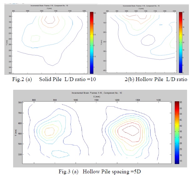
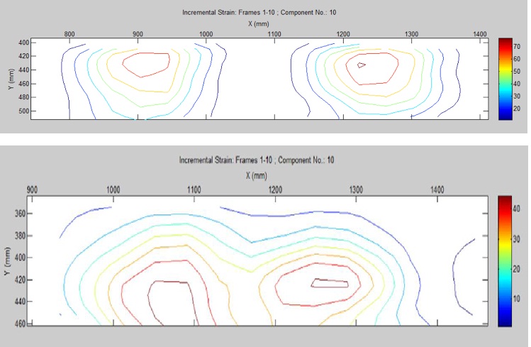
Fig. 3(a) and 3 (b) also shows that the area of influence for pile group is also more for hollow pile groups than solid pile groups.
The experiments carried out in the present study are limited. The different areas that are to be exploredin the future are
1. Study deformation of soil around the single piles and pile groups.
2. Understand the effect of interference zone and group efficiency.
3. Study the stresses developed in the embedded soil using isobars.
4. Study the effect of relative density and gradation of infill materialwhich contribute to mechanical behaviour of the entire system.
From the experimental study, the following points are summarized:
1. PIV technique is successful in capturing soil-pile interaction.
2. Zone of influence of solid pile captured in the image is in agreement with that in literature.
3. Zone of influence is more for hollow pile rather than solid pile though flexural rigidity is same.
