


Published on Apr 02, 2024
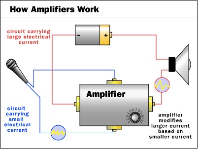
An Amplifier is a device which is used for multiplying the Amplitude of variation of alternating voltage or current or power. An Amplifier, may have two inputs , one from the external world as a microphone or an antenna or a TV camera, and another input obtained from its own output. The input obtained from the output is normally small but the input from the external world may be larger so that the output would follow the form of the input from the eternal world to the amplifier, unlike the oscillator which has an internal world of its own apart from it energy supply system as all amplifiers need an external energy supply. With amplifiers one needs to be careful what input to apply and also how much and what polarity one applies feedback from the output otherwise one can finish with, an oscillator, or a constant voltage or constant current power supply and not a signal amplifier that gives out a larger form or a quantity, proportional to waveform of the input.
To construct amplifier using n-p-n transistor and study its current gain and identify its active region
An Amplifier is a device which is used for multiplying the Amplitude of variation of alternating voltage or current or power.
Here’s a diagram of how an amplifier works:
A transistor is a semiconductor device used to amplify or switch electronic signals and electrical power. It is composed of semiconductor material with three terminals for connection to an external circuit.
Emitter (E): It is the left hand side thick layer of the transistor which is heavily doped;
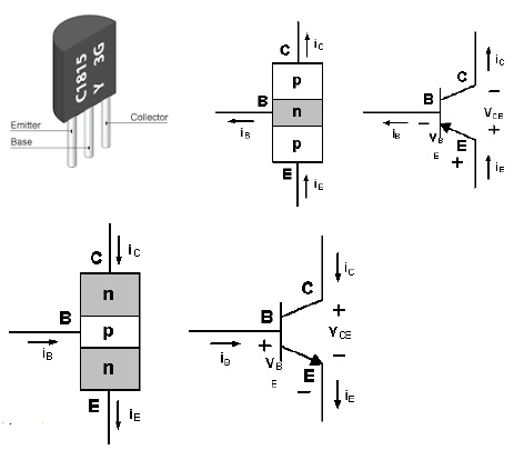
Base (B): It is a central thin layer of transistor which is lightly doped;
Collector (C): It is the right hand side thick layer of the transistor which is moderately doped;
A p-n-p junction transistor is obtained by growing a thin layer of thin layer of n-type semi-conductor in between two relatively thick layers of p-type semi-conductor.
A n-p-n junction transistor is obtained by growing a thin layer p-type semi-conductor in between two relatively thick layers of n-type semi-conductor.
In this experiment, we will use a n-p-n transistor.
The common-emitter amplifier is designed so that a small change in voltage (Vin) changes the small current through the base of the transistor; the transistor's current amplification combined with the properties of the circuit mean that small swings in Vin produce large changes in Vout.
Various configurations of single transistor amplifier are possible, with some providing current gain, some voltage gain, and some both.
From mobile phones to televisions, vast numbers of products include amplifiers for sound reproduction, radio transmission, and signal processing. The first discrete-transistor audio amplifiers barely supplied a few hundred milliwatts, but power and audio fidelity gradually increased as better transistors became available and amplifier architecture evolved.
Modern transistor audio amplifiers of up to a few hundred watts are common and relatively inexpensive.
1. A n-p-n transistor;
2. Two battery eliminators;
3. Two High resistance Rheostats;
4. Connecting Wires;
5. Two One Way keys;
6. Two Ammeters;
7. Two Voltmeters;
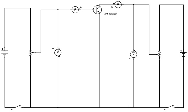
• Connect the apparatus accordingly as shown in the circuit diagram.
• Determine the least count and the zero errors of voltmeters and ammeters.
• Keep the potential of the battery Vb at a low voltage
• Make all the connections neat, clean and tight.
• Note the Least count
• Increase the voltage from input battery Vb from 0 to 0.6 V.
• Note the input current at this point.
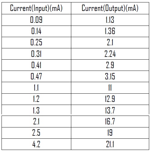
• Now increase the input current by changing the resistance of rheostat and record the corresponding output current.
• Ensure that the input voltage does not exceed 1 V (input and output voltage will change correspondingly).
• Plot the readings of the current taken in the graph of Current (inp) vs Current (out).
1. Least count of Voltmeter (Vi)= 0.2 V
2. Range of Voltmeter (Vi)= 10 V
3. Zero Error of voltmeter (Vi)= 0 V
4. Least count of Voltmeter (Vo)= 0.2 V
5. Range of Voltmeter (Vo)= 10 V
6. Zero Error of Voltmeter (Vo)= 0 V
1. Least count of Milliammeter (inp)= 2 mA
2. Range of Milliammeter (inp)= 100 mA
3. Zero error of Milliammeter (inp)= 0 mA
4. Least count of Milliammeter (out)= 10 mA
5. Range of Milliammeter (out)= 500 mA
6. Zero error of Milliammeter (out)= 0 mA
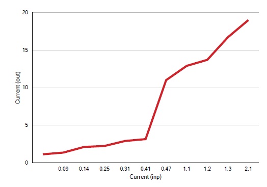
1. As seen from the graph, the active region with maximum current amplification is from 0.41A to 2.0A.
2. Current gain(amplification)(β) = 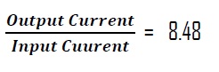
3. A minimum of 0.6V needs to be provided as activation voltage to input part of circuit, i.e., base-emitter (BE) section.
With the experiments carried out in the laboratory to study the characteristics of the NPN transistor proved the aim defined in the report. The NPN transistor has got current amplification in the tune of 8.5 in the region of 0.4 to 2 ma.
• colorado.edu/physics/phys3330/PDF/Experiment7.pdf
• en.wikipedia.org/wiki/Transistor#Transistor_as_an_amplifier
• en.wikipedia.org/wiki/Common_emitter
• 230nsc1.phy-astr.gsu.edu/hbase/electronic/npnce.html
• tedpavlic.com/teaching/osu/ece327/lab1_bjt/lab1_bjt_transistor_basics.pdf
• hyperphysics.phy-astr.gsu.edu/hbase/solids/trans.htm
