


Published on Nov 30, 2023
First wheelchair model evolved long back in 18th century, but rapid development in this field initiated since mid of 20th century. Since then, many varieties of models had been designed, extending into broad range of products. This project involves the design of an ergonomically designed electric wheelchair for domestic use by Indian old aged people. Stair climbing functionality is embedded in the design through its structure and mechanism. The product mainly consists of 3 modules viz. seat, links and frame. Anthropometric measures are considered in the dimensioning of seat. The frame and wheels are designed and developed through the equations generated from the statistical data of dimensions of staircases in Indian houses. Focus is laid on different parameters such as form, functionality, technology and architecture of the product. The design is validated by developing Digital Mockups of individual parts are generated in CATIA and are assembled to form the final product. Necessary simulations of the product are generated in virtual environment of CATIA.
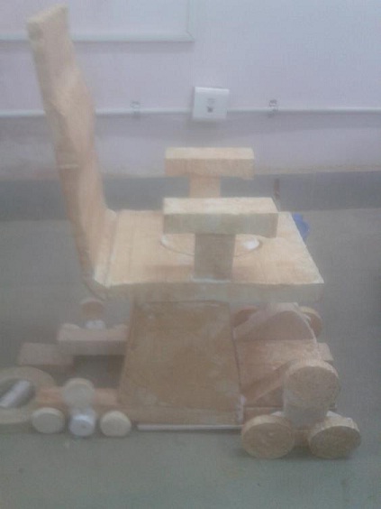
The physical and focused prototype indicating the structure and functionality is developed using thermocol material. Here wheel carriers are made in RP (Fused Deposition Modelling) using ABS (Acrylo Butadiene Styrene) material. Wheelchair is embedded with some additional features like integrated commode facility, after gathering costumer requirements from different subjects.
A motorized wheelchair or electric-powered wheelchair is a wheelchair that is propelled by means of an electric motor rather than manual power. Motorized wheelchairs are useful for those who are not able to impel a manual wheelchair or who may need to employ a wheelchair for distances or over terrain which would be strenuous in a manual wheelchair. They may also be used not just by people with conventional mobility impairments, but also by people with cardiovascular and fatigue based conditions. Electric wheelchairs have enhanced the quality of life for many people with physical disabilities through the mobility they afford. The selection of power chair will rely on many factors; including the kind of surface setting the chair will be driven over, the need to settle thresholds and curbs, and clearance widths in accustomed environment. The most fundamental job of the chair is to take input from the user, usually in the form of a small joystick, and decipher that motion into power to the wheels to move the person in the preferred direction. The last few years have seen abundant improvements and models that give the user unmatched control of the wheelchair in terms of both user effort and vehicle aptitude
The objective of this project is to analyze and prototype a motorized wheelchair based on extensive fact findings and research on existing models, technology used, market scenario and customer requirements. The course of our work begins with the planning phase involving initial research, literature review and background study. It is followed by concept generation phase that includes evaluating customer requirements, outlining specifications and generating concept designs. Next comes the system level design in which product architecture is defined and parts are modeled in CATIA. The fourth phase is detailed design phase where we focus on design for assembly and manufacturing and simulation in virtual environment. In the final phase, we progress towards prototyping and testing a feasible model.
The methodology for this project began with market study of the product under consideration. This involved extensive evaluation of the various types of wheelchairs available in the market and a precise overview of the Indian market scenario.
The foremost electric wheelchair was invented by George Klein with the purpose to help the wounded soldiers of the World War II. With time, it has evolved into many designs and forms. The power chairs comprise a range of functions like reclining, tilting, seat elevation, chin controller, hand controller and many more. Some of the models are portable that is they can be disassembled and carried along while travelling. The electric wheelchair is characteristically categorized into three categories
The front wheel powered chair: It is a power chair for indoor purposes. This is a four wheel driven chair and is most flexible among the lot.
The rear wheel powered chair: It is a power chair facilitated for outdoors. Being rear wheeled, they are appropriate for rugged roads.
Mid wheel powered chair: This electric wheelchair is apposite for indoors but it has sturdy steering functions
The heavy duty power wheelchair has been shown in Figure 3.1. It is designed to be used for outdoor rationale and can be customized on the basis of individual necessities.. It can be used for travelling over coarse surfaces. These power chairs can be transferred only by the aid of lifts and ramps.
This type of power wheelchair can be easily conveyed by virtue of its light weight and thus it can be disassembled fast and hassle free. Because of its compact size, it is apt for slender doorways and halls.
These power wheelchairs, shown in fig 3.3 are mostly unique because of their higher battery array. Being unfold able, it requires lifts during travel. It is suitable for both outdoor and indoor travel. This wheelchair ensures a smooth and stable traverse.
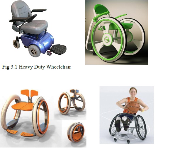
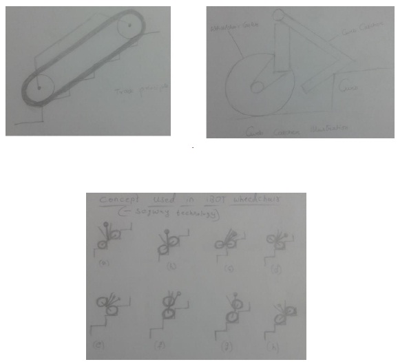
This wheelchair is operated like a habitual manual wheelchair. While the user pushes on the hand rims, force sensors in the rims perceive the user’s physical effort and adjoin supplementary power to the wheels. Thus the physical movement is analogous to power steering in a car. A self-balancing technology is integrated that places the user in the centre of gravity while balancing on two wheels. The obliteration of the requirement for castor wheels leads to more condensed and maneuverable medium. The lithium ion batteries which power the electric servo motors are situated in the base of each of the hub less wheels and are rechargeable, giving the vehicle a range of approximately 20km with one charge. Wide and ergonomically viable push rims allow an easier grip
These chairs are tailored for sports – such as basketball, or tennis or bowling
The frame consists of a chassis that carries two motorized locomotion units, a support for two electrical gear-motors, two idle triple wheels units and a battery pack. The chassis consists mainly of two tubular structures, connected by means of crossbars; two triangular tubular structures on the front support the triple wheel units. Connection points are hinges for the linkage mechanism. The triple wheel units consist of a spider, rotating around a central axis, with three idle wheels placed at its vertices. Wheel size was chosen on the basis of the consideration that large wheels can better absorb vibrations caused by uneven terrain, while small wheels reduce overall dimensions. Accordingly, larger wheels were selected for the locomotion unit and for the pivoting wheel, which are in contact with the ground most of the time, while smaller ones were chosen for the triple wheel units, in contact with the terrain only during the stair climbing operation.
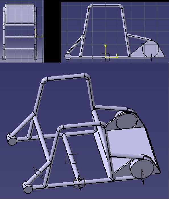
The dimensions of the frame are calculated according to the space constraints. These space constraints are obtained from height of base of seat from ground and dimensions of chair. Seat height is based upon the anthropometric measurements of the parameter ‘Knee height’. According to the Indian anthropometric measurements, 95th percentile of knee height in sitting posture is 55cm. Assuming 15cm as clearance, a total of 70cm of gap is considered. Therefore, frame dimensions are decided upon the space constraints of (48X63X70) cm.
A gear motor is used as locomotion unit and this motion is transmitted to the clustered wheels. This motor is mounted on a support provided by the frame as shown. The dimensions and specifications of gear motor are obtained from standard motors available. A gear motor of 750 watt power and 1:64 reduction gear ratio is used.
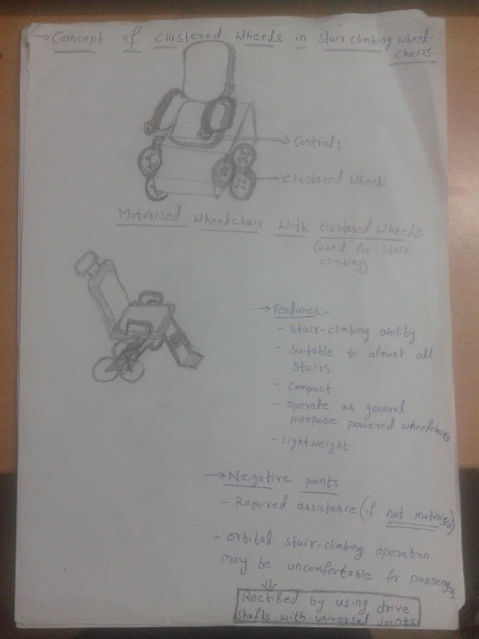
Here a clustered wheel concept is being developed in order to accommodate stair climbing feature. Three wheels are arranged in a triangular array, such that centers of each of the wheels coincide with vertices of an equilateral triangle. Now the side of an equilateral triangle (s) and radius of the wheel (r) are calculated using certain equations, which are described below. In the following equations, step heights and depths are assumed to lie in the range between (152-203)mm and (254-330) mm respectively. These are taken from ergonomic standards. As the wheelchair being designed is intended for domestic use, steps would rather be even and so their heights and depths are approximately taken as 150mm and 250mm respectively. Also the evenness of these stairs led to the equilateral configuration of wheel arrangement
In order to keep the base of the seat horizontal while climbing up or down the stairs, a linkage mechanism is provided connecting the seat and frame together. This mechanism is designed based on the second inversion of 4-bar linkage mechanism. It is similar to whit worth quick return mechanism. Here, a closed loop control is provided with mini servo motor being connected to the 2nd link. Strain gauges are used to feedback appropriate angle to be rotated to acquire stability and making no couple to act on the wheelchair. Here, mini motor keeps the seat in stable position bringing the Centre of gravity down.
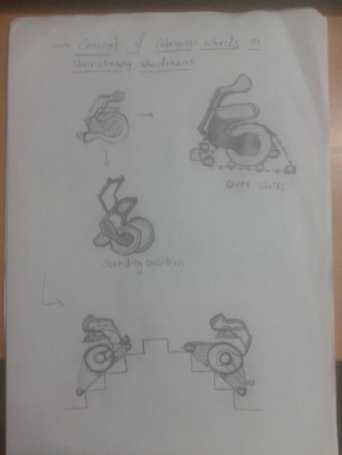
The linkage mechanism generates relative motion between the frame and the seat. During stair climbing operations it is required to accomplish three different tasks: moving the seat backwards, reorienting it and lifting up the pivoting wheel. When the seat is moved backwards, the centre of mass of the wheelchair is placed in a safe position, and overturning is thus prevented.
Initially the power from the battery flows to the gear motor, which is arranged together with battery in an enclosed box. Now the gear motor rotates along with the shaft attached, with appropriately reduced RPM according to the specified reduction ratio of motor. Here ‘differential gears’ are used to transmit the motion from rotating shaft to the wheels with the flexibility for left and right (exterior and interior) wheels to move at different speeds. This accommodates turning of the wheelchair when required.
The differential gear has three jobs:
To aim the engine power at the wheels.
To act as the final gear reduction in the vehicle, slowing the rotational speed of the transmission one final time before it hits the wheels.
To transmit the power to the wheels while allowing them to rotate at different speeds.
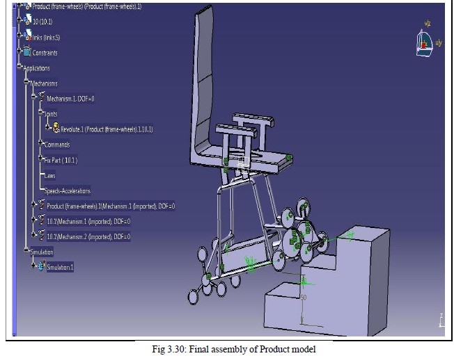
The digital and physical mock-ups are developed based on the discussed equations in the sections above. These are as shown in figures 4.1 and 3.31. Here the dimensions of the physical model are scaled to half of original dimensions as it is intended to serve as focused physical prototype depicting the structure and basic functionality. The dimensions of original complete model developed in CATIA are as given below.
In the designed model, there are variations in proportional dimensional scaling. These are due to the different percentiles of anthropometric parameters considered in the design of individual features of chair. These percentiles to be considered are based on subjective perceptions arrived at by subjective analyses. Also the design of wheels and wheel carrier are suitable to limited range of staircase dimension variations. As the product is targeted for domestic use, the regularity in staircases are assumed.
The mechanism for engagement and disengagement of shaft to the sun gear and the wheel carrier are to be developed further, to accommodate the switching between stair climbing mode and moving on flat ground mode. This could be provided either manually or automatically by setting the maximum limit for torque in flat ground mode.
This project involves the design of an ergonomically designed electric wheelchair for domestic use by Indian old aged people. Stair climbing functionality was the main focus in its structure and mechanism. The product covered 3 modules viz. seat, links and frame. Seat dimensions were calculated following the Indian Anthropometric standards. The frame and wheels are designed and developed through the mathematical calculations based upon from the statistical data of dimensions of staircases in Indian houses. Form, functionality, technology and architecture of the product are also evaluated. Digital Mockups of individual parts were developed in CATIA and assembled to form the final product. The stair climbing mechanism is simulated in virtual environment. The physical and focused prototype indicating the structure and functionality is developed using thermocol material. The wheel carriers are developed by using Rapid Prototyping technique (Fused Deposition Modelling) using ABS (Acrylo Butadiene Styrene) material. Wheelchair is embedded with some additional features like integrated commode facility, after gathering costumer requirements from different subjects.
1. N.M. Abdul Ghani, M.O. Tokhi, A.N.K Nasir, S.Ahmad., 2011. Control of a Stair Climbing Wheelchair 1 (4) 204-208
2. Giuseppe Quaglia⁎, Walter Franco, Riccardo Oderio., 2011. Wheelchair.q, A Motorized Wheelchair with Stair Climbing Ability 46 (1) 1602-1605
3. L J Murray., Study of Stair Climbing Assistive Mechanisms for the Disabled., 18-31
4. Lockton D., 2004 Wheelchair Drive 241 (1) 5-68
