


Published on Nov 30, 2023
Magneto abrasive flow machining (MAFM) is a new technique in machining. The orbital flow machining process has been recently claimed to be another improvement over AFM, which performs three-dimensional machining of complex components. These processes can be classified as hybrid machining processes (HMP)-a recent concept in the advancement of non-conventional machining.
The reasons for developing a hybrid machining process is to make use of combined or mutually enhanced advantages and to avoid or reduce some of the adverse effects the constituent processes produce when they are individually applied.
In almost all non-conventional machining processes such as electric discharge machining, electrochemical machining, laser beam machining, etc., low material removal rate is considered a general problem and attempts are continuing to develop techniques to overcome it.
The present paper reports the preliminary results of an on-going research project being conducted with the aim of exploring techniques for improving material removal (MR) in AFM. One such technique studied uses a magnetic field around the work piece.
Magnetic fields have been successfully exploited in the past, such as machining force in magnetic abrasive finishing (MAF), used for micro machining and finishing of components, particularly circular tubes. The process under investigation is the combination of AFM and MAF, and is given the name Magneto Abrasive Flow Machining (MAFM).
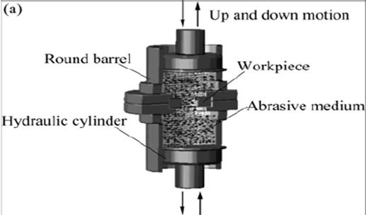
An experimental set-up is designed and fabricated, it is shown in fig:6.1. It consisted of two cylinders
(1) containing the medium along with oval flanges
(2). The flanges facilitate clamping of the fixture
(3) that contains the work piece
(4) and index the set-up through 180° when required. Two eye bolts
(5) also support this purpose. The setup is integrated to a hydraulic press
(6). The flow rate and pressure acting on piston of the press were made adjustable. The flow rate of the medium was varied by changing the speed of the press drive whereas the pressure acting on the medium is controlled by an auxiliary hydraulic cylinder
(7), which provides additional resistance to the medium flowing through the work piece.
The resistance provided by this cylinder is adjustable and can be set to any desired value with the help of a modular relief valve
(8). The piston
(9) of the hydraulic press then imparts pressure to the medium according to the passage size and resistance provided by opening of the valve. As the pressure provided by the piston of the press exceeds the resistance offered by the valve, the medium starts flowing at constant pressure through the passage in the work piece.
The upward movement of the piston (i.e. stroke length) is controlled with the help of a limit switch. At the end of the stroke the lower cylinder completely transfers the medium through the work piece to the upper cylinder.
The position of the two cylinders is interchanged by giving rotation to the assembly through 180° and the next stroke is started. Two strokes make up one cycle. A digital counter is used to count the number of cycles. Temperature indicators for medium and hydraulic oil are also attached.
