


Published on Nov 30, 2023
Intrinsically in home and office appliances like light and fan are controlled manually, which leads to power wastage. Even though there is no usage then also left ON and even when the appliances are in use their operation is not controlled by environmental conditions like temperature variations and daylight. By making a smart automated controlling system for appliances we can save the power by some amount. In this paper we are providing a solution for preventing the wastage of power in an adequate and cost effective way. Our system consists of a biometric electronic door lock and power saving module. When the user finger print matches in door lock, the power saving module is switched ON. The power saving module switches the appliances in the room based on the presence of the person. It also controls the power delivered to fan and light according to temperature of room and natural daylight intensity.
The work of the home automation is still under development phase and we have not come across any effective and low cost automation system.
As the Fig. 1 shows that the amount of power that can be saved by smart control. The comparisons of power consumption at home with and without smart control are shown in Table 1[2]. Finally the total power consumed can be reduced about 18% by using smart control system.

A smart door locks home automation system [1]. A remote based home automation system developed by Bluetooth technology [3]. A Zigbee based home automation system and Wi-Fi integrated through a common home gateway have been developed earlier [4] in which the appliances of home can monitored and controlled from door lock with Zigbee network. Most of the systems developed earlier are dependent on the motion sensing of the user in the room which can fail if users movements are minimum (sitting or sleeping). Another problem is the cost of wireless network. The use of Zigbee and other protocol devices increases the cost of the system. The system we propose is free from these problems. Instead of just sensing the motion, the system also counts the number of persons in the room and decides the room occupancy status to prevent any errors. Instead of just ONOFF switching, it also monitors their intensity through a power control drive according to the daylight availability and temperature of the room. For creating a wireless network we have used low cost RF modules that is easy to use and easily available.
1. ARM7 TDMI-S LPC2129 controller
2. Dc Power supply unit
3. 16×2 LCD
4. Temperature sensor LM 35
5. Passive infrared sensor
6. LDR sensor OPT 101
7. GSM modem
8. RF module
9. Relays
10. Finger print sensor (R303A)
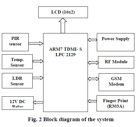
This system explains complete operation. It includes hardware peripherals like, ARM7 TDMI- S (LPC 2148), temperature sensor, PIR Sensor, LDR Sensor, RF module, GSM modem, R303A, DC Relay, Power Supply, 16x2 LCD.
16/32-bit ARM7TDMI-S microcontroller in a tiny LQFP64 package.
16KB on-chip static RAM.
128/256KB on-chip flash program memory.
128bit wide interface/ accelerator enable high speed 60MHz operation.
External 8, 16 or 32 bit bus.
Two/four interconnected CAN interfaces with advanced acceptance filters.
Flash programming takes 1ms per 512 byte line.
Single sector or full chip erase takes 400ms.
4/8 channel (64/144 pin package) 10 bit A/D converter with conversion time as low as 2.44ms.
In-System Programming (ISP) and In-Application Programming (IAP) via on-chip boot-load software.
Dual Power Supply - CPU operating voltage range of 1.65V to 1.95V (1.8V +/- 8.3%).
- I/O power supply range of 3.0V to 3.6V (3.3V +/- 10%).
When compared to Zigbee based devices RF module is easily available and also implement at low cost. Transmitter can be powered from 3 to 12V power supply while receiver accepts 5V. Modules do not require addition components just apply power and connect single data line to send information to or from. The data is serial send and received through these modules from microcontroller. The module uses pulse width modulation method.
TX and RX modules are tuned to work correctly at 433.92MHz.
High speed data transfer rates (1200 – 9600 baud).
Line of sight range up to 250 feet.
Power required: 3.3- 5V DC @ 10mA.
Operating temperature: 32 to 158 °F (0 to 70 °C).
A Passive Infrared (PIR) is a sensor detects the presence of nearby objects without any physical contact. PIR sensors are used as proximity sensor. A proximity sensor generally emits an electromagnetic or electrostatic field or beam of electromagnetic radiation and looks for changes in the field or return signal.
• Complete, fully functional motion detection.
• Wide 5 m x 5 m, 60 degree detection pattern.
• Sensitivity control via simple hardware configuration.
• SLEEP mode for low power applications.
• No temperature compensation required
• Operates from 2.7 V to 3.6 V power supply
• Simple 8-pin interface.
• Standard operating temperature: 0 °C to 70 °C.
The light sensor used is OPT 101 it provides analogue output proportional to the light intensity which is converted to digital by analogue to digital converter (ADC) available in the microcontroller. Similarly temperature sensor LM 35 also gives analogue output that is converted to digital by ADC. The measured analogue value is compared to some preset value in software. After analyzing the sensor readings signal is sent to the receiver for changing the power delivered to the load.
A relay is an electrical switch that uses an electromagnet to move the switch from OFF to ON position instead of person moving switch. It takes relatively small amount of power to turn on a relay but the relay can control something that draws the much power.
This door lock includes finger print sensor. Here sensor used is R303A, Fingerprints are one of many forms of biometrics, used to identify individuals and verify their identity. The analysis of fingerprints for matching purposes generally requires the comparison of several features of the print pattern. These include patterns, which are aggregate characteristics of ridges, and minutia points, which are unique features found within the patterns. It is also necessary to know the structure and properties of human skin in order to successfully employ some of the imaging technologies.
GSM (Global System for Mobile communications) is the technology that underpins most of the world's mobile phone networks [5]. GSM is an open, digital cellular technology used for transmitting mobile voice and data services. GSM operates in the 900MHz and 1.8GHz bands GSM supports data transfer speeds of up to 9.6 kbps, allowing the transmission of basic data services such as SMS. The GSM standard is intended to address these problems. In the current work, SIM300 GSM module is used, it is shown in fig.2. The SIM300 module is a Tri-band GSM/GPRS solution in a compact plug in module featuring an industry-standard interface.
Single supply voltage 3.2V to 4.5V.
MT, MO, CB, text and PDU mode, SMS storage: SIM card.
SIM300 tri-band.
Supported SIM Card: 1.8V, 3V.
This module is operates on AT command. AT command is an abbreviation for Attention command that is recognized by GSM Module. "AT command set for GSM Mobile Equipment” describes the Main AT commands to communicate via a serial interface with the GSM subsystem of the phone. The GSM modem is interfaced to microcontroller through UART0 serial communication
As below Fig. 6 shows the working diagram of smart system. Here locking and unlocking of the door is done by using finger print sensor and GSM modem. Initially consider the complete system is in disable state. If user wants to enter the house, then the user suppose to verify his finger print pattern with pre stored pattern in its own flash memory. If the verification is invalid then it displays unauthorized access. Otherwise it unlocks the door and enables the power saving module by turning the power supply ON. In case if the user is authorized but his finger print pattern is not stored in flash memory then owner of the house will send the control message OPEN to GSM Modem, now GSM Modem receives the message and verifies, if invalid then the message will be discarded. Otherwise it unlocks the door.
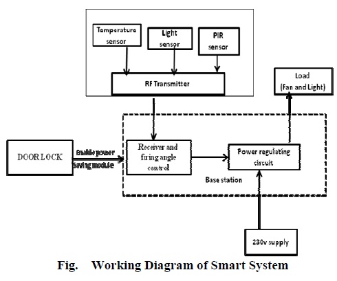
Once the power saving module is enabled the RF transmitter which is connected to microcontroller sends their respective sensors readings to the base station. The sensors which are transmitted their readings to RF transmitter are temperature sensor LM35, light sensor OPT101 and PIR sensor. These sensors are used to decide the environmental condition and requirement of the user. The PIR sensor decides whether the room is occupied or not. The readings which are transmitted to base station which contains RF receiver and power control circuit.
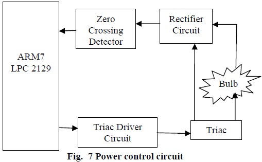
The AC control circuit obtains signal from the microcontroller for changing the firing angle delay of the Triac circuit. Fig. 7 shows the block diagram of AC control circuit. The zero-crossing detector (ZCD) gives high pulse whenever the AC supply signal crosses the x-axis. The ZCD circuit consists of 4N35 and 12V transformer. The signal from the ZCD is used to interrupt the microcontroller. After getting interrupted it waits for a period of firing angle. After a delay of firing angle(α) the microcontroller triggers the triac through opto-coupler MOC3010. The readings from RF transmitter are used to calculate the firing angle. By changing firing angle we cannot only switch the appliances ON and OFF but can also vary the power delivered to them. So if the temperature is low the power delivered to the fan will be lowered, similarly if the natural intensity is low i.e. during evening the power delivered to the light will be increased. Thus we can save the power by using smart control system.
The keilmicroVision4 IDE (integrated development environment) combines project management, make facilities, source code editing, program debugging, and complete simulation in one powerful environment. The μVision development platform is easy-to-use and helping you quickly create embedded programs that work. The μVision editor and debugger are integrated in a single application that provides a seamless embedded project development environment
N x P semiconductors produce a range of microcontrollers that feature both on- chip Flash memory and ability to be reprogrammed using in system programming technology. Flash Magic is Windows software from the Embedded Systems Academy that allows easy access to all the ISP features provided by the devices. The features include:
1. Erasing Flash memory (individual blocks or whole device).
2. Programming the Flash memory.
3. Modifying the boot vector and status byte.
4. Reading Flash memory.
5. Reading signature bytes.
6. Reading and writing security bits.
7. Direct load new baud rate (high speed communication).
8. Sending commands to place device in boot loader mode.
Flash Magic only obtains access to the selected COM Port when ISP operations are being performed. This means that other applications that need to use the COM Port, such as debugging tools, may be used while Flash Magic is loaded.
Embedded C is a high level language, which includes Many aspects of the ANSI (American National Standard Institute) C programming language. Extensions for the programming language C to support embedded processors, enabling portable and efficient application programming for embedded systems. Embedded C is a set of language extensions for the C Programming language by the C Standards committee to address commonality issues that exist between C extensions for different embedded systems. Historically, embedded C programming requires nonstandard extensions to the C language in order to support exotic features such as fixedpoint arithmetic, multiple distinct memory banks, and basic I/O operations.
Finally total power can be consumed by using smart controlling system. If one unit of power is saved at consumer level we can save two units of power at power station. Thus the importance of power saving and need of a smart system increases. Such a smart power saving system is suggested in the paper that can save power and increase comfort level of the user with minimum expenditure. We implemented the biometric door lock system that increases the security level. The components used in the system like microcontroller, sensors and wireless transceivers are readily available and cheap. This system can installed in many applications such as Automated irrigation systems, industrial automation, security systems etc.
[1] Yong Tae Park, Pranesh Sthapit and Jae-Young Pyun, ”Smart Digital Door Lock for the Home Automation” TENCON 2009 978-1-4244- 4547-9/09/26.00 2009 IEEE.
[2] Dhiren Tejani, Ali Mohammed A. H. Al-Kuwari and Vidyasagar Potdar ”Energy Conservation in a Smart Home” 5th IEEE International Conference on Digital Ecosystems and Technologies (IEEE DEST 2011), 31 May -3 June 2011, Daejeon, Korea.
[3] Kwang Yeol Lee, Jae Weon Choi ”Remote-Controlled Home Automation System via Bluetooth Home Network” 5th SICE Annual Conference in Fukui, August 4-6,2003 Fukui University, Japan.
[4] Khusvinder Gill, Shuang-Hua Yang, Fang Yao, and Xin Lu”A ZigBee-Based Home Automation System” IEEE Transactions on Consumer Electronics, Vol. 55, No. 2, MAY 2009.
[5] Raghu Ram.Gangi, Subhramanya Sarma.Gollapudi “Locker opening and closing system using RFID, finger Print, password and GSM” (IJETTCS 2013), Volume 2 Issue 2, March – April 2013.
