

Updated on May 29, 2026
Information displays are the primary medium through which text and images generated by computer and other electronic systems are delivered to end-users. While early computer systems were designed and used for tasks that involved little interactions between the user and the computer, today's graphical and multimedia information and computing environments require information displays that have higher performance, smaller size and lower cost.
The market for display technologies also has been stimulated by the increasing popularity of hand-held computers, personal digital assistants and cellular phones; interest in simulated environments and augmented reality systems; and the recognition that an improved means of connecting people and machines can increase productivity and enhance the enjoyment of electronic entertainment and learning experiences.
For decades, the cathode ray tube has been the dominant display device. The cathode ray tube creates an image by scanning a beam of electrons across a phosphor-coated screen, causing the phosphors to emit visible light. The beam is generated by an electron gun and is passed through a deflection system that scans the beam rapidly left to right and top to bottom, a process called Rastering. A magnetic lens focuses the beam to create a small moving dot on the phosphor screen. It is these rapidly moving spots of light ("pixels") that raster or "paint" the image on the surface of the viewing screen. Flat panel displays are enjoying widespread use in portable computers, calculators and other personal electronics devices. Flat panel displays can consist of hundreds of thousands of pixels, each of which is formed by one or more transistors acting on a crystalline material.
In recent years, as the computer and electronics industries have made substantial advances in miniaturization, manufacturers have sought lighter weight, lower power and more cost-effective displays to enable the development of smaller portable computers and other electronic devices. Flat panel technologies have made meaningful advances in these areas. Both cathode ray tubes and flat panel display technologies, however, pose difficult engineering and fabrication problems for more highly miniaturized, high-resolution displays because of inherent constraints in size, weight, cost and power consumption. In addition, both cathode ray tubes and flat panel display are difficult to see outdoors or in other setting where the ambient light is brighter than the light emitted from the screen. Display mobility is also limited by size, brightness and power consumption.
As display technologies attempt to keep pace with miniaturization and other advances in information delivery systems, conventional cathode ray tube and flat panel technologies will no longer be able to provide an acceptable range of performance characteristics, particularly the combination of high resolution, high level of brightness and low power consumption, required for state-of-the-art mobile computing or personal electronic devices.
It is really interesting to note why this family of imaging systems score better than the conventional display systems.
One problem with conventional helmet mounted display image sources is the low luminance levels they produce. Most liquid crystal array image sources have insufficient luminance levels for operation in a see-through display. The VRD, however, does not contain individual Lambertian (or nearly Lambertian) pixel emitters (liquid crystal cells or phosphors) as do most LCD arrays and CRT's.
The only light losses in the VRD result from the optics (including the scanners and fiber coupling optics). There is no inherent tradeoff, however, between resolution and luminance as is true with individual pixel emitters. In individual pixel emitters, a smaller physical size increases resolution but decreases luminance. In the Virtual Retinal Display, intensity of the beam entering the eye and resolution are independent of each other. Consequently, the VRD represents a major step away from the traditional limitations on display brightness.
As mentioned in the previous section there is a tradeoff between resolution and brightness in screen based displays. As resolution requirements increase, the number of picture elements must increase in a screen based display. These greater packing densities become increasingly difficult to manufacture successfully. The VRD overcomes this problem because the resolution of the display is limited only by the spot size on the retina. The spot size on the retina is determined primarily by the scanner speed, light modulation bandwidth, and imaging optics.
One limiting aspect in the manufacture of liquid crystal array image generators is the yield and reliability of the hundreds of thousands of individual liquid crystal cells present in these displays. For a liquid crystal array display to function properly at all times, each picture element must function properly. The Virtual Retinal Display requires only constant functionality from the light sources and the scanners. As resolution increases in virtual image displays, liquid crystal arrays will contain more and more individual liquid crystal cells. The Virtual Retinal Display will gain an increasing advantage over liquid crystal array image generators in terms of yield as resolution demands increase in the future.
The theoretical size for horizontal and vertical scanners plus light sources for the VRD is smaller than the size of conventional liquid crystal array and CRT image sources. A typical size for a liquid crystal array image generator for helmet mounted display applications is one inch by one inch. The Mechanical Resonant Scanner used in this project was approximately 1 [cm] by 2 [cm]. Furthermore, the problem of scanner size has not been directly addressed. Further size reduction is certainly possible. It should be noted that light sources for a smaller, usable full color VRD must be much smaller than the sources used in this project. The potential size of light emitting diodes and diode lasers indicate that these sources show greatest promise for future systems in terms of size.
Moreover, it will be quite surprising to know that the original stereographic display, or the three dimensional view as the eye means it, can be accomplished only by an imaging system like the one proposed above.
In a conventional display a real image is produced. The real image is either viewed directly or, as in the case with most head-mounted displays, projected through an optical system and the resulting virtual image is viewed. The projection moves the virtual image to a distance that allows the eye to focus comfortably. No real image is ever produced with the VRD. Rather, an image is formed directly on the retina of the user's eye. A block diagram of the VRD is shown in the figure below.
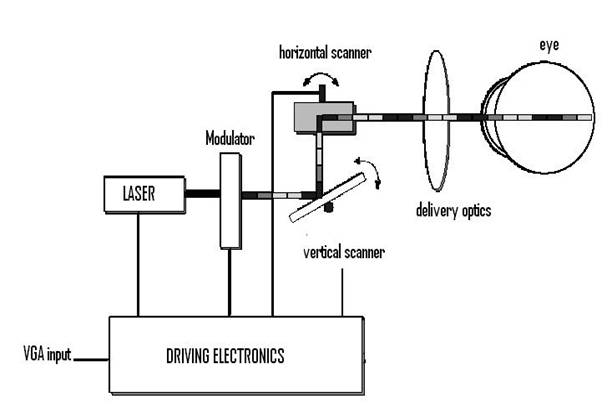
To create an image with the VRD a photon source (or three sources in the case of a color display) is used to generate a coherent beam of light. The use of a coherent source (such as a laser diode) allows the system to draw a diffraction limited spot on the retina. The light beam is intensity modulated to match the intensity of the image being rendered. The modulation can be accomplished after the beam is generated. If the source has enough modulation bandwidth, as in the case of a laser diode, the source can be modulated directly.
The resulting modulated beam is then scanned to place each image point, or pixel, at the proper position on the retina. A variety of scan patterns are possible. The scanner could be used in a calligraphic mode, in which the lines that form the image are drawn directly, or in a raster mode, much like standard computer monitors or television. Our development focuses on the raster method of image scanning and allows the VRD to be driven by standard video sources. To draw the raster, a horizontal scanner moves the beam to draw a row of pixels. The vertical scanner then moves the beam to the next line where another row of pixels is drawn.
After scanning, the optical beam must be properly projected into the eye. The goal is for the exit pupil of the VRD to be coplanar with the entrance pupil of the eye. The lens and cornea of the eye will then focus the beam on the retina, forming a spot. The position on the retina where the eye focuses the spot is determined by the angle at which light enters the eye. This angle is determined by the scanners and is continually varying in a raster pattern. The brightness of the focused spot is determined by the intensity modulation of the light beam. The intensity modulated moving spot, focused through the eye, draws an image on the retina. The eye's persistence allows the image to appear continuous and stable.
Finally, the drive electronics synchronize the scanners and intensity modulator with the incoming video signal in such a manner that a stable image is formed
The following sections detail some of the advantages of using the VRD as a personal display.
The VRD does not require an intermediate image on a screen as do systems using LCD or CRT technology. The only required components are the photon source (preferably one that is directly modulatable), the scanners, and the optical projection system. Small photon sources such as a laser diode can be used. As described below the scanning can be accomplished with a small mechanical resonant device developed in the HITL. The projection optics could be incorporated as the front, reflecting, surface of a pair of glasses in a head mount configuration or as a simple lens in a hand held configuration. HITL engineers have experimented with single piece Fresnel lenses with encouraging results. The small number of components and lack of an intermediate screen will yield a system that can be comfortably head mounted or hand held.
Resolution of the current generation of head mounted and hand held display devices is limited by the physical parameters associated with manufacturing the LCDs or CRTs used to create the image. No such limit exists in the VRD. The limiting factors in the VRD are diffraction and optical aberrations from the optical components of the system, limits in scanning frequency, and the modulation bandwidth of the photon source.
A photon source such as a laser diode has a sufficient modulation bandwidth to handle displays with well over a million pixels. If greater resolution is required multiple sources can be used.
Currently developed scanners will allow displays over 1000 lines allowing for the HDTV resolution systems. If higher resolutions are desired multiple sources, each striking the scanning surface at a different angle, can be used.
The field of view of the VRD is controlled by the scan angle of the primary scanner and the power of the optical system. Initial inclusive systems with greater than 60 degree horizontal fields of view have been demonstrated. Inclusive systems with 100 degree fields of view are feasible. See through systems will have somewhat smaller fields of view. Current see through systems with over 40 degree horizontal fields of view have been demonstrated.
Color will be generated in a VRD by using three photon sources, a red, a green, and a blue. The three colors will be combined such that they overlap in space. This will yield a single spot color pixel, as compared to the traditional method of closely spacing a triad, improving spatial resolution.
The intensity seen by the viewer of the VRD is directly related to the intensity emitted by the photon source. Intensity of a photon source such as a laser diode is controlled by the current driving the device. Proper control of the current will allow greater than ten bits of intensity resolution per color.
Brightness may be the biggest advantage of the VRD concept. The current generations of personal displays do not perform well in high illumination environments. This can cause significant problems when the system is to be used by a soldier outdoors or by a doctor in a well lit operating room. The common solution is to block out as much ambient light as possible. Unfortunately, this does not work well when a see through mode is required.
The VRD creates an image by scanning a light source directly on the retina. The perceived brightness is only limited by the power of the light source. Through experimentation it has been determined that a bright image can be created with under one microwatt of laser light. Laser diodes in the several milliwatt range are common. As a result, systems created with laser diode sources will operate at low laser output levels or with significant beam attenuation.
The VRD delivers light to the retina efficiently. The exit pupil of the system can be made relatively small allowing most of the generated light to enter the eye. In addition, the scanning is done with a resonant device which is operating with a high figure of merit, or Q, and is also very efficient. The result is a system that needs very little power to operate.
The traditional head-mounted display used for creating three dimensional views projects different images into each of the viewer's eyes. Each image is created from a slightly different view point creating a stereo pair. This method allows one important depth cue to be used, but also creates a conflict. The human uses many different cues to perceive depth. In addition to stereo vision, accommodation is an important element in judging depth. Accommodation refers to the distance at which the eye is focused to see a clear image. The virtual imaging optics used in current head-mounted displays place the image at a comfortable, and fixed, focal distance. As the image originates from a flat screen, everything in the virtual image, in terms of accommodation, is located at the same focal distance. Therefore, while the stereo cues tell the viewer an object is positioned at one distance, the accommodation cue indicates it is positioned at a different distance.
With the VRD it is theoretically (this is currently in the development stage) possible to generate a more natural three dimensional image. The VRD has an individual wavefront generated for each pixel. It is possible to vary the curvature of the wavefronts. Note that it is the wavefront curvature which determines the focus depth. This variation of the image focus distance on a pixel by pixel basis, combined with the projection of stereo images, allows for the creation of a more natural three-dimensional environment.
Systems have been produced that operate in both an inclusive and a see through mode. The see through mode is generally a more difficult system to build as most displays are not bright enough to work in a see through mode when used in a medium to high illumination environment where the luminance can reach ten thousand candela per meter squared. As discussed above, this is not a problem with the VRD.
In the VRD a light source is modulated with image information, either by direct power ("internal") modulation or by an external modulator. The light is passed through an x-y scanning system, currently the MRS and a galvanometer. Light from the scanner pair enters an optical system, which in present implementations of the VRD forms an aerial image and then uses and eyepiece to magnify and relay this image to infinity.
| Are you interested in this topic.Then mail to us immediately to get the full report.
email :- contactv2@gmail.com |
