


Updated on Mar 21, 2026
The VISNAV system uses a Position Sensitive Diode (PSD) sensor for 6 DOF estimation. Output current from the PSD sensor determines the azimuth and elevation of the light source with respect to the sensor. By having four or more light source called beacons in the target frame at known positions the six degree of freedom data associated with the sensor is calculated.
The beacon channel separation and demodulation are done on a fixed point digital signal processor (DSP) Texas Instruments TMS320C55x [2] using digital down conversion, synchronous detection and multirate signal processing techniques. The demodulated sensor currents due to each beacon are communicated to a floating point DSP Texas Instruments TMS320VC33 [2] for subsequent navigation solution by the use of colinearity equations.
Among other competitive systems [3] a differential global positioning system (GPS) is limited to midrange accuracies, lower bandwidth, and requires complex infrastructures. The sensor systems based on differential GPS are also limited by geometric dilution of precision, multipath errors, receiver errors, etc.These limitations can be overcome by using the DSP embedded VISNAV system
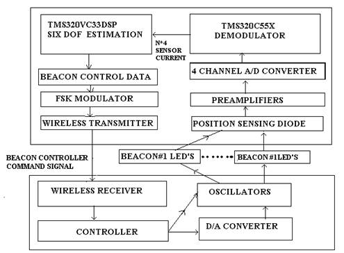
This the general block diagram of VISNAV system. A sinusoidal carrier of approximately 40 kHz frequency is applied to modulate each beacon LED drive current. the resulting induced PSD signal current then vary sinusoidally at approximately same frequency and are demodulated to recover the currents that are proportional to the beacon light centroid.
The output of PSD is very weak. So we have to amplify these signals by using a preamplifier. After amplification this signal is fed to four channel analog to digital converter. This converts the four channels of analog data into digital form. And is then fed to the DSP, TMS320C55x [2] to demodulate the signal. After the demodulation the four channel data is fed to the Six Degree Of Freedom estimator, which uses DSP for estimation. From this point we get the sensor co-ordinates.
As discussed earlier that the controlling of beacons to avoid the problem of saturation we uses the beacon control data which is given by the DSP, TMS320VC33 [2]. This control data is in digital form. We use radio link to communicate the control data from the sensor electronics module to the beacon controller module
| Are you interested in this topic.Then mail to us immediately to get the full report.
email :- contactv2@gmail.com |
