


Published on Apr 02, 2024
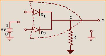
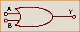
To make an OR gate using diodes
Switches, wires, diodes, LED bulb, battery (9V)
1. When both A and B are earthed (i.e. connected to low input 0), both the diodes do not conduct and no voltage develops across R. Therefore the voltage at C is zero with respect to earth. Hence the output Y is 0 (in levels).
2. When A = 0 and B = 1 (i.e., connected to positive terminal), the diode D2 conducts but D1 does not. Since D2 is ideal, no voltage drop takes place across D2 and a full voltage drop of 5V takes place across R at C, +5V with respect to earth. Therefore Y is 1 (in level).
3. When A = 1 and B = 0, D1 conducts but D2 does not. For the same reason as stated above the output Y is 1 (in level).
4. When A = 1 and B = 1, both diodes conducts since the diodes are ideal and connected in parallel, the voltage drop across R cannot exceed 5V, with C at +5V with respect to earth. Hence the output Y will be 1 (in level)
1) IC 4049: This Logic Gate circuit uses NOT gate from CMOS I.C CD 4049. CD 4049 contains 6 independent NOT gate in one package; we have used here (a) one only. Advantage of using Logic gate is that data can be easily send to other digital interface device ie one can easily fed data to computer using parallel port or for further processing .
2) LDR: To detect the present of an object we have used LDR and a source of light. LDR is a special type of resistance whose value depends on the brightness of the light which is falling on it. It has resistance of about 1 mega ohm when in total darkness, but a resistance of only about 5k ohms when brightness illuminated. It responds to a large part of light spectrum.
3) BUZZER: Sound is produced through buzzer.
4) 9v BATTERY: The output is powered by 9v battery.
5) SWITCH: It is used to allow or disallow current to pass through the circuit.
6) LED: It is Light Emitting Diode which emits light when forward biased.
Hence, when the light beam is made to fall on the LDR and is interrupted, the resistance of LDR increases and IC – 4049 will produce a loud sound in the speaker.
