


Published on Nov 30, 2023
In modern electronics, electronics remote control system is well known system. Infrared Remote Control kit's available in the market are quite expensive and it some one wishes to assemble one, their IC's may not be easily available. More over for simple ON-OFF function such as controlling a lamp or fan we do not need very complex circuit. The IR remote control circuit using photodiode and phototransistor sensor suffer from major drawback of being affected by ambient light and a very low range.
The IR remote control circuit described here can be used for any simple ON-OFF function. This system has memories application than other remote control system. The advantage is that this circuit is absolutely free form ambient light interference and provides control range of any to focusing lens. The components use in this system is in so convenient manner that whole assemble is easier to built. This reduce complex city of the system.
The advantage of this circuit lies in the fact that it can easily be converted into a multichannel remote control system. The system comprise two unit transmitter, Receiver Both transmitter and receiver can be assembled on a general purpose PCB. Transmitter section consist of power supply, on oscillator and in output stage including IR LEDS in the transmitter section IC 555 is wired as an a stable multivibrator with a Centre frequency of about 36 KHZ. The transmitter is powered from a GP 22 size gv. battery.
The receiver uses IR sensor module which is commonly used in colour T.V. for sening IR Singal from transmitter section. The IR singal from the transmitter sensed by sensor and it's output at pin and goes low which is in turn switch on transistor T1 (BC 557) consequently capacitors start charging through resister R5, when voltage across capacitor C8 reaches about 3.5V IC 2 (Decade counter 4017) receive a clock pulse at pin 14 and it's output at pin 2 goes high.
This result in forward biasing of transistor to (be 148) which energies a really connected at it's collector. The output of IC 2 (pin 2) is also used for lighting LED, indicating presence of singal for this circutary 12 v-0-12v 25 mA transformer is used for supplying the power & IC 7805 is used for 5 v regulation purpose at it's output.
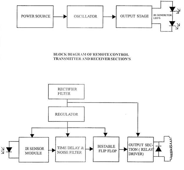
Block diagram of the circuit is shown in Figure. Transmitter section consists of a power supply, an oscillator and an output stage, where as the receiver section comprises power supply, an infrared detector module, time delay circuit with noise filter, bistable flip flop and a output section. The complete schematic diagrams of the transmitter and receiver sections are shown in Figures respectively.
In the transmitter section ICI (555) is wired as a stable multi-vibrator with a center frequency of about 36 KH Z . When switch SI is pressed, the circuit gets energized. Output of ICI is a square wave. The two infrared LEDS connected at its output transmit IR beams modulated at the same frequency (36 KH Z ). The oscillator frequency can be shifted slightly by adjusting preset VRI
