


Updated on May 29, 2026
Block shear is a limit state that should be accounted for during the design of steel tension members. This failure mechanism combines a tensile failure on one plane and a shear failure on a perpendicular plane.
It is important for a design equation not only to predict the capacity reliably, but also to predict accurately the failure mode. In this study, we begin with an overview of tension members, their behaviour and design strength which is affected by yielding, fracture or block shear.
Different codal provisions in IS 800: 2007 for tension members have been dealt, with a special focus on block shear and its failure mechanism. Latest specifications on block shear in AISC 2005 and Eurocode 3 have also been explained so as to provide a broader view of the standards being adopted worldwide to check failure of structures by block shear.
Recent developments in block shear research have also been discussed, both finite element analysis and experimental programs. Block shear failure is not just limited to bolted connections and keeping this in mind, research works conducted on block shear in bolted as well as welded steel sections have been presented herein. Finally, a numerical on block shear has been solved using the provisions in IS 800, AISC 2005 and Eurocode 3. The results obtained shows the given section to be safe from block shear failure; with the Eurocode provisions predicting the lowest design strength (though more than the applied reaction), AISC value being the highest and IS 800 values somewhere in the middle range. Based on these findings and studies, a conclusion has been arrived at and presented at the end of the report.
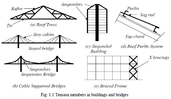
Tension members are linear members in which axial forces act so as to elongate (stretch) the member. A rope, for example, is a tension member. Tension members carry loads most efficiently, since the entire cross section is subjected to uniform stress. Unlike compression members, they do not fail by buckling. Ties of trusses [Fig 1.1 (a)], suspenders of cable-stayed and suspension bridges [Fig.1.1 (b)], suspenders of buildings systems hanging from a central core [Fig.1.1 (c)] (used in earthquake prone zones as a way of minimising inertia forces on the structure), and sag rods of roof purlins [Fig 1.1 (d)] are other examples of tension members.
Tension members can have a variety of cross sections. Any cross-sectional configuration may be used, because for any given material, the only determinant of the strength of a tension member is the cross-sectional area. Circular rods and rolled angle shapes are frequently used. Built-up shapes either from plates, rolled shapes, or a combination of plates and rolled shapes are sometimes used when large loads must be resisted.
The single angle and double angle sections [Fig 1.2(a)] are used in light roof trusses as in industrial buildings. The tension members in bridge trusses are made of channels or I sections, acting individually or built-up [Figs. 1.2(b) and 1.2(c)]. The circular rods [Fig. 1.2 (d)] are used in bracings designed to resist loads in tension only. They buckle at very low compression and are not considered effective. Steel wire ropes [Fig.1.2 (e)] are used as suspenders in the cable suspended bridges and as main stays in the cable-stayed bridges.
The strength of tension members based on IS 800:2007 is the minimum of the following three categories as stated below:
Yielding of the gross section, i.e. yielding of the tension member over the member length away from the connection.
Fracture of the effective net section, i.e. fracture of the tension member in the connection region.
Block shear rupture, i.e. tearing out of the connection due to the combination of tensile and shear failure.
The design strength of tension members are not always controlled by factor of safety or by the strength of the bolts or welds with which they are connected. They may instead be controlled by block shear strength. In block shear mode, the failure of the member occurs along a path involving tension on one plane and shear on a perpendicular plane along the fasteners. When a tensile load applied to a particular connection is increased, the fracture strength of the weaker plane approaches. This plane does not fail instantly, because it is restrained by the stronger plane. The load can be increased until the fracture strength of the stronger plane is reached and during this time, the weaker plane yields. The total strength of the connection equals the fracture strength of the stronger plane plus the yield strength of the weaker plane. Thus, it is not realistic to add the fracture strength of the other plane to determine the block shear resistance of a particular member.
When a tensile load applied to a particular connection is increased, the fracture strength of the weaker plane approaches. This plane does not fail instantly, because it is restrained by the stronger plane. The load can be increased until the fracture strength of the stronger plane is reached and during this time, the weaker plane yields. The total strength of the connection equals the fracture strength of the stronger plane plus the yield strength of the weaker plane. Thus, it is not realistic to add the fracture strength of the other plane to determine the block shear resistance of a particular member.
It is also required to check the block shear failure mode around the periphery of welded connections. Examples of block shear failures including failures in welded connections are given in Fig. 1.7. It can be observed as shown in Fig. 1.7(a) that the gusset plate may fail in tension on the net area of section a-a, and in Fig. 1.7(c) it may fail on the gross area of section a-a. The angle member in Fig. 1.7(a) may also separate from the gusset plate by shear on net area 1-2 combined with tension on net area 2-2 as shown in Fig. 1.7(b). A similar fracture of the welded connection of Fig. 1.7(c) is shown in Fig 1.7(d).
The fracture of a gusset plate for a double angle member or of one of the gusset plates for an I-section [Fig. 1.7(e)] is shown in Fig. 1.7(f). All these failures [Figs. 1.7(b), (d) and (f)] are called block shear failures. However, it should be noted that no net areas are involved in the failure of welded connections [Fig. 1.7(c)]. Therefore, in applying Eqn. 1.3(a) Atg is to be used instead of Atn; and in Eqn. 1.3(b), Avn is to be replaced by Avg.
IS 800: 2007 assumes that when one plane, either tension or shear, reaches ultimate strength the other plane develops full yield. This assumption results in two possible failure mechanisms in which the controlling mode is the one having a smaller fracture strength term. In the first mechanism, it is assumed that failure load is reached when rupture occurs along the net tension plane and full yield is developed along the gross shear plane. Conversely, the second failure mode assumes that rupture occurs along the net shear plane while full yield is developed at the gross tension plane [Refer Eqns. 1.3(a) and (b)]. Since there is no reserve of any kind beyond the ultimate resistance, an additional multiplier of 0.09 has been introduced in the said equations.
Such a high margin of safety has been traditionally used in design when considering the fracture limit state than for yielding limit state. The 0.90 factor was included in the strength equation based on a statistical evaluation of a large number of test results for net section failure of plate.equations. Such a high margin of safety has been traditionally used in design when considering the fracture limit state than for yielding limit state. The 0.90 factor was included in the strength equation based on a statistical evaluation of a large number of test results for net section failure of plate.
| Are you interested in this topic.Then mail to us immediately to get the full report.
email :- contactv2@gmail.com |
