


Published on Jan 09, 2026
A moving train contains energy, known as kinetic energy, which needs to be removed from the train in order to cause it to stop. The simplest way of doing this is to convert the energy into heat. The conversion is usually done by applying a contact material to the rotating wheels or to discs attached to the axles. The material creates friction and converts the kinetic energy into heat.
The wheels slow down and eventually the train stops. The material used for braking is normally in the form of a block or pad.
The vast majority of the world's trains are equipped with braking systems which use compressed air as the force used to push blocks on to wheels or pads on to discs. These systems are known as "air brakes" or "pneumatic brakes". The compressed air is transmitted along the train through a "brake pipe". Changing the level of air pressure in the pipe causes a change in the state of the brake on each vehicle. It can apply the brake, release it or hold it "on" after a partial application. The system is in widespread use throughout the world.
An alternative to the air brake, known as the vacuum brake, was introduced around the early 1870s, the same time as the air brake. Like the air brake, the vacuum brake system is controlled through a brake pipe connecting a brake valve in the driver's cab with braking equipment on every vehicle. The operation of the brake equipment on each vehicle depends on the condition of a vacuum created in the pipe by an ejector or exhauster. The ejector, using steam on a steam locomotive, or an exhauster, using electric power on other types of train, removes atmospheric pressure from the brake pipe to create the vacuum. With a full vacuum, the brake is released. With no vacuum, i.e. normal atmospheric pressure in the brake pipe, the brake is fully applied.
The pressure in the atmosphere is defined as 1 bar or about 14.5 lbs. per square inch. Reducing atmospheric pressure to 0 lbs. per square inch, creates a near perfect vacuum which is measured as 30 inches of mercury, written as 30 Hg. Each 2 inches of vacuum therefore represents about 1 lb. per square inch of atmospheric pressure.
In the UK, vacuum brakes operated with the brake pipe at 21 Hg, except on the Great Western Railway which operated at 25 Hg. The vacuum in the brake pipe is created and maintained by a motor-driven exhauster. The exhauster has two speeds, high speed and low speed. The high speed is switched in to create a vacuum and thus release the brakes. The slow speed is used to keep the vacuum at the required level to maintain brake release. It maintains the vacuum against small leaks in the brake pipe. The vacuum in the brake pipe is prevented from exceeding its nominated level (normally 21 Hg) by a relief valve, which opens at the setting and lets air into the brake pipe to prevent further increase.
The momentum of a moving body increases with weight and speed of the body as these factors increase improvements in the brake become so important. The adhesion of the wheels and speed of the train are the main factors that determines the total retarding power. The maximum retarding force applied by the brake blocks at wheels depends upon the coefficient of friction between the wheels and the rail and the component of the weight of the wagon on the wheels. Mathematically the retarding force F can be expressed as
F = ? * W
Where ? = the coefficient of friction
W = component of weight of wagon on the wheels
If the coefficient of friction becomes equal to unity then the retarding force will be equal to the weight of the wagon. Also the deceleration equals the acceleration due to gravity. Then the braking efficiency is 100%. This is the theoretical limit for braking efficiency. Highly efficient brakes giving a large deceleration might injure the passengers due to sudden stopping of the train .More over this will cause the brake shoes to wear rapidly and their is always the risk of derailment. The braking efficiencies usually vary from 50% to 80%, which enables the train to stop safely with in a reasonable distance. The equations used for the calculations of acceleration can also be used for calculating the braking distance except to the accelerating force becomes the braking force Fb
The brake force Fb = p* ? * ?
Where p = brake shoe pressure
? = co-efficient of fricton between brake shoe and wheel
? efficiency of braking
This diagram shows the principal parts of the vacuum brake system as applied to an electric or diesel train. Click on the name to see a description of the part. The systems used on steam locomotives were somewhat different.
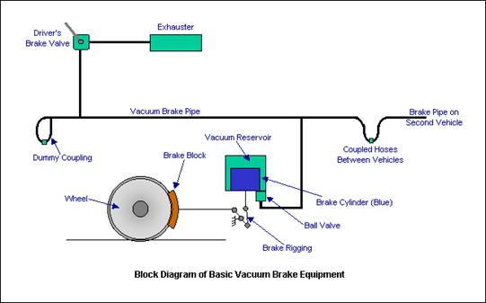
The means by which the driver controls the brake. The brake valve will have (at least) the following positions: "Release", "Running", "Lap" and "Brake On". There may also be a "Neutral" or "Shut Down" position, which locks the valve out of use. The "Release" position connects the exhauster to the brake pipe and switches the exhauster to full speed. This raises the vacuum in the brake pipe as quickly as possible to get a release.
In the "Running" position, the exhauster keeps running but at its slow speed. This ensures that the vacuum is maintained against any small leaks or losses in the brake pipe, connections and hoses.
"Lap" is used to shut off the connection between the exhauster and the brake pipe to close off the connection to atmosphere after a brake application has been made. It can be used to provide a partial release as well as a partial application, something not possible with the original forms of air brake.
"Brake On" closes off the connection to the exhauster and opens the brake pipe to atmosphere. The vacuum is reduced as air rushes in.
Some brake valves were fitted with an "Emergency" position. Its operation was the same as the "Brake On" position, except that the opening to atmosphere was larger to give a quicker application.
A two-speed rotary machine fitted to a train to evacuate the atmospheric pressure from the brake pipe, reservoirs and brake cylinders to effect a brake release. It is usually controlled from the driver's brake valve, being switched in at full speed to get a brake release or at slow speed to maintain the vacuum at its release level while the train is running. Exhausters are normally driven off an electric motor but they can be run directly from a diesel engine.
The vacuum-carrying pipe running the length of the train, which transmits the variations in pressure required to control the brake. It is connected between vehicles by flexible hoses, which can be uncoupled to allow vehicles to be separated. The use of the vacuum system makes the brake "fail safe", i.e. the loss of vacuum in the brake pipe will cause the brake to apply.
At the ends of each vehicle, a dummy coupling point is provided to allow the ends of the brake pipe hoses to be sealed when the vehicle is uncoupled. The sealed dummy couplings prevent the vacuum being lost from the brake pipe.
The brake pipe is carried between adjacent vehicles through flexible hoses. The hoses can be sealed at the outer ends of the train by connecting them to dummy couplings.
Each vehicle has at least one brake cylinder. Sometimes two or more are provided. The movement of the piston contained inside the cylinder operates the brakes through links called "rigging". The rigging applies the blocks to the wheels. The piston inside the brake cylinder moves in accordance with the change in vacuum pressure in the brake pipe. Loss of vacuum applies the brakes, restoration of the vacuum releases the brakes.
The operation of the vacuum brake relies on the difference in pressure between one side of the brake cylinder piston and the other. In order to ensure there is always a source of vacuum available to operate the brake, a vacuum reservoir is provided on, or connected to the upper side of the piston. In the simplest version of the brake, shown above, the brake cylinder is integral with the vacuum reservoir. Some versions of the brake have a separate reservoir and a piped connection to the upper side of the piston.
This is the friction material which is pressed against the surface of the wheel tread by the upward movement of the brake cylinder piston. Often made of cast iron or some composition material, brake blocks are the main source of wear in the brake system and require regular inspection to see that they are changed when required.
This is the system by which the movement of the brake cylinder piston transmits pressure to the brake blocks on each wheel. Rigging can often be complex, especially under a passenger car with two blocks to each wheel, making a total of sixteen. Rigging requires careful adjustment to ensure all the blocks operated from one cylinder provide an even rate of application to each wheel. If you change one block, you have to check and adjust all the blocks on that axle.
The ball valve is needed to ensure that the vacuum in the vacuum reservoir is maintained at the required level, i.e. the same as the brake pipe, during brake release but that the connection to the brake pipe is closed during a brake application. It is necessary to close the connection as soon as the brake pipe vacuum is reduced so that a difference in pressure is created between the upper and lower sides of the brake cylinder piston. See the next paragraph - Operation on Each Vehicle.
This diagram shows the condition of the brake cylinder, ball valve and vacuum reservoir in the release position. The piston is at the bottom of the brake cylinder, the brake cylinder is open at the top so that it is in direct connection with the vacuum reservoir.
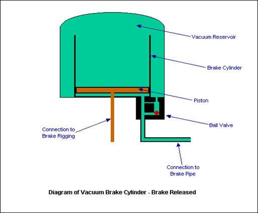
A vacuum has been created in the brake pipe, the vacuum reservoir and underneath the piston in the brake cylinder. The removal of atmospheric pressure from the system has caused the ball valve to open the connection between the vacuum reservoir and the brake pipe. The fall of the piston to the bottom of the brake cylinder causes the brake blocks to be released from the wheels.
| Are you interested in this topic.Then mail to us immediately to get the full report.
email :- contactv2@gmail.com |
