


Published on Apr 02, 2024
Electronic Toll Collection is a generally mature technology that allows for electronic payment of highway tolls. It takes advantage of vehicle-to-roadside communication technologies to perform an electronic monetary transaction between a vehicle passing through a toll station and the toll agency. This project is implemented using the innovative technology of Radio Frequency Identification (RFID).
Radio-frequency identification (RFID) is a technology that uses communication via electromagnetic waves to exchange data between a terminal and an electronic tag attached to an object, for the purpose of identification and tracking.
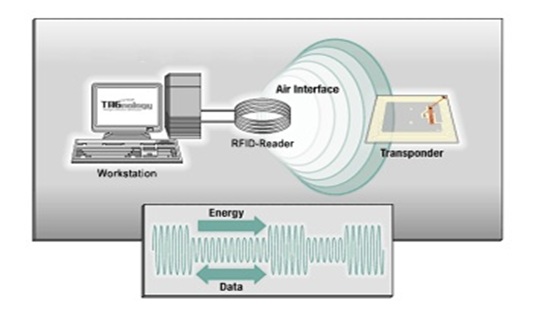
An RFID system consists of a reader and transponders. Transponders (derived from the words "transmitter" and "responder") are attached to the items to be identified. They are often called "tags". Radio Frequency Identification (RFID) involves contact less reading and writing of data into an RFID tag's non-volatile memory through an RF signal. The reader emits an RF signal and data is exchanged when the tag comes in proximity to the reader signal. The RFID tag derives its power from the RF reader signal and does not require a battery or external power source.
Each vehicle will be provided with an RFID tag. This transponder (tag) stores the unique ID of the vehicle and related information. When interrogated by a reader, it responds with that data over a radio frequency link. The readers are fixed in the toll gates. So when the vehicle comes near the reader, the data from the tags can be easily read by the readers. This data is passed to the computer and thus the cash can be deducted from the user’s account
RFID is a wireless link to uniquely identify tags. These systems communicate via radio signals that carry data either unidirectional or bidirectional. The tag is energized by a time-varying electromagnetic radio frequency (RF) wave that is transmitted by the reader. This RF signal is called carrier signal. When tag is energized the information stored in the tag is transmitted back to the reader. This is often called backscattering. By detecting the backscattering signal, the information stored in the tag can be fully identified. RFID systems are comprised of two main components RF reader and RF Tag
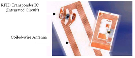
The RFID tag, or transponder, is located on the object to be identified and is the data carrier in the RFID system. Typical transponders (transmitters/responders) consist of a microchip that stores data and a coupling element, such as a coiled antenna, used to communicate via radio frequency communication. Transponders may be either active or passive.
Active transponders have an on-tag power supply (such as a battery) and actively send an RF signal for communication while passive transponders obtain all of their power from the interrogation signal of the transceiver and either reflect or load modulate the transceiver’s signal for communication. Most transponders, both passive and active, communicate only when they are interrogated by a transceiver.
Active RFID and Passive RFID are fundamentally different technologies. While both use radio frequency energy to communicate between a tag and a reader, the method of powering the tags is different. Active RFID uses an internal power source (battery) within the tag to continuously power the tag and its RF communication circuitry, whereas Passive RFID relies on RF energy transferred from the reader to the tag to power the tag. While this distinction may seem minor on the surface, its impact on the functionality of the system is significant
Passive RFID either 1) reflects energy from reader or 2) absorbs and temporarily stores a very small amount of energy from the reader’s signal to generate its own quick response. In either case passive RFID operation requires very strong signals from the reader and the signal strength required from the tag is constrained to very low levels by the limited energya. On the other hand active RFID allows very low level signals to be received by the tag, and the tag can generate high level signals back to the reader, driven from its internal power source. Active RFID tag is continuously powered, whether in the reader field or not.
The selection of active or passive tag affect factors like range of communication, data storage capacity ,sensor ability etc. If the tag is active the reader can spot more tags within seconds than the passive tag, but as the cost is compared the passive tags are cheaper than the active tags. The life of the passive tags are more than the active tag because , active tag requires tag power supply within the chip.
The different frequencies that the tag can work are;
Low frequency (LF) - These tags work at a frequency of around 125 kHz and have a reading range of less than 50 cm. The reading speed is relatively low and the tags are relatively insensitive to interference. This band enjoys relative freedom from regulatory limitations because it has not been reserved as an ISM frequency range, although in this frequency interval other systems operate typically for aeronautical and marine navigational services. Tags in this frequency range have been using now in applications such as access control and animal tracking.
High frequency (HF) - Operate worldwide at 13.56 MHz and can be read at distances of around one meter, but tags use more energy than low frequency tags. Existing uses include tracking books in libraries and baggage at airports. At around 13.56MHz, electromagnetic fields can propagate through water and tissue but cannot penetrate metals. Antennas are made simply of turns of coils of small radius.
Ultra-High frequency (UHF)- These tags work at a range between 433 and 2000 MHz and can be read from further away and at higher speed than HF tags. This makes this frequency the most appropriate for supply chain applications, such as tracking pallets and case
The interrogator consists of a reader and data processing subsystem. The RFID reader, or transceiver, which may be able to both read data from and write data to a transponder. The data processing subsystem which utilizes the data obtained from the transceiver in some useful manner.
Typical transceivers (transmitter/receivers), or RFID readers, consist of a radio frequency module, a control unit, and a coupling element to interrogate electronic tags via radio frequency communication. In addition, many transceivers are fitted with an interface that enables them to communicate their received data to a data processing subsystem, e.g., a database running on a personal computer. The use of radio frequencies for communication with transponders allows RFID readers to read passive RFID tags at small to medium distances and active RFID tags at small to large distances even when the tags are located in a hostile environment and are obscured from view. The figure shows handheld and stationary reader modules.
The basic components of an RFID system combine in essentially the same manner for all applications and variations of RFID systems. All objects to be identified are physically tagged with transponders. The type of tag used and the data stored on the tag varies from application to application.
The RF field generated by a tag reader (the energy transmitter) has three purposes:
1. Induce enough power into the tag coil to energize the tag:
2. Provide a synchronized clock source to the tag:
3. Act as a carrier for return data from the tag:
Passive RFID tags obtain their operating power from the electromagnetic field of the reader’s communication signal. The limited resources of a passive tag require it to both harvest its energy and communicate with a reader within a narrow frequency band as permitted by regulatory agencies. Passive tags typically obtain their power from the communication signal either through inductive coupling or far field energy harvesting.
Inductive coupling uses the magnetic field generated by the communication signal to induce a current in its coupling element (usually a coiled antenna and a capacitor). The current induced in the coupling element charges the on-tag capacitor that provides the operating voltage, and power, for the tag. In this way, inductively coupled systems behave much like loosely coupled transformers. Consequently, inductive coupling works only in the near-field of the communication signal. For a given tag, the operating voltage obtained at a distance d from the reader is directly proportional to the flux density at that distance.
There is a fundamental limitation on the power detected a distance d away from a reader antenna. In a loss less medium, the power transmitted by the reader decreases as a function of the inverse square of the distance from the reader antenna in the far field. A reader communicates with and powers a passive tag using the same signal. The fact that the same signal is used to transmit power and communicate data creates some challenging trade-offs
The electronic toll Collection systems are a combination of completely automated toll collection systems and semi-automatic lanes. Various traffic and payment data are collected and stored by the system as vehicles pass through. The different technologies involved are logically integrated with each other but remain flexible for upgrades. They also include sophisticated video and image capturing equipment for full-time violation enforcement. So this basic arrangement developed by us will applicable for the future developments in road transport by proper modifications. RFID systems have a secure place in the automatic identification sector. The system can made free from the challenges and will be cost effective in near future.
1. www.rfidjournal.com
2. www.microchip.com
3. www.rfida.com
4. www.alldatasheet.com
5. Design with PIC microcontrollers, Pearson Education Pte. Ltd, Second Edition -John.B.Peatman
6. Op-Amps and Linear Integrated Circuits, Prentice Hall of India Private Ltd -Ramakanth.A.Gayakwad
| Are you interested in this topic.Then mail to us immediately to get the full report.
email :- contactv2@gmail.com |
