


Updated on May 29, 2026
An accurate electric current transducer is a key component of any power system instrumentation. To measure currents power stations and substations conventionally employ inductive type current transformers with core and windings.
For high voltage applications, porcelain insulators and oil-impregnated materials have to be used to produce insulation between the primary bus and the secondary windings. The insulation structure has to be designed carefully to avoid electric field stresses, which could eventually cause insulation breakdown.
The electric current path of the primary bus has to be designed properly to minimize the mechanical forces on the primary conductors for through faults. The reliability of conventional high-voltage current transformers have been questioned because of their violent destructive failures which caused fires and impact damage to adjacent apparatus in the switchyards, electric damage to relays, and power service disruptions.
With short circuit capabilities of power systems getting larger, and the voltage levels going higher the conventional current transformers becomes more and more bulky and costly also the saturation of the iron core under fault current and the low frequency response make it difficult to obtain accurate current signals under power system transient conditions.
In addition to the concerns, with the computer control techniques and digital protection devices being introduced into power systems, the conventional current transformers have caused further difficulties, as they are likely to introduce electro-magnetic interference through the ground loop into the digital systems. This has required the use of an auxiliary current transformer or optical isolator to avoid such problems.
It appears that the newly emerged Magneto-optical current transformer technology provides a solution for many of the above mentioned problems.
The MOCT measures the electric current by means of Faraday Effect, which was first observed by Michael Faraday 150 years ago. The Faraday Effect is the phenomenon that the orientation of polarized light rotates under the influence of the magnetic fields and the rotation angle is proportional to the strength of the magnetic field component in the direction of optical path.
The Magneto-Optical current transformer is based on the Faradays effect. Michael Faraday discovered that the orientation of linearly polarized light was rotated under the influence of the magnetic field when the light propagated in a piece of glass, and the rotation angle was proportional to the intensity of the magnetic field. The concept of Faraday Effect could be understood from the Fig.1.
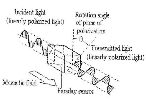
Fig. 1
Generally, this phenomenon can be described as follows:
= V dl …………Eq(1)
‘’ is the Faraday rotation angle,
‘V’ is the Verdet constant of magneto-optical material
‘B’ is the magnetic flux density along the optical path
‘l’ is the optical path
When the linearly polarized light encircles a current carrying conductor eq(1) can be rewritten as according to Ampere’s law as
=nVI ………….Eq(2)
‘I ‘is the current to be measured,
‘’ is the permeability of the material,
‘n’ is the number of turns of the optical path.
The Faraday effect outlined in eq(2) is a better format to apply to an MOCT, because the rotation angle in this case is directly related to the enclosed electric current. It rejects the magnetic field signals due to external currents which are normally quite strong in power system.
The typical application of the Faraday effect to an MOCT is clear from fig(2). A polarizer is used to convert the randomly polarized incident light into linearly polarized light. The orientation of the linearly polarized light rotates an angle after the light has passed through the magneto-optical material because of Faraday Effect. Then another polarization prism is used as an analyzer, which is 45 0 oriented with the polarizer, to convert the orientation variation of the polarized light into intensity variation of the light with two outputs, and then these two outputs are send to photo detectors. The purpose of using the analyzer is that photo detectors can only detect the intensity of light, rather than the orientation of polarizations. The output optical signals from the analyzer can be described as,
P1 = (1 + Sin 2 )
P2 = (1 - Sin 2 )
P0 is the optical power from the light source,
is the Faraday rotation angle,
P1 and P2 are the optical power delivered by the detectors.
In order to properly apply Eq(2) in the MOCT design by making the optical path wrap around the current carrying conductor, the optical path has to be folded by reflections. Total internal reflections and metal reflections are good ways to achieve this. However reflections introduce phase shift; hence change the polarization state of the light. The optical prism has to be designed to keep the light going through the MOCT linearly polarized.
In order to stimulate the behavior of the polarized light reflect through the glass prism of an MOCT, ie to maintain the light traveling through the glass prism to be linearly polarized and also for the analysis of the effects of dielectric and metal reflections on the linearly polarized light, a computer programme is written in FORTARN language. Stimulation results include information such as polarization state change at each reflection and the overall responsibility of the optical sensor.
| Are you interested in this topic.Then mail to us immediately to get the full report.
email :- contactv2@gmail.com |
