
Published on Apr 02, 2024
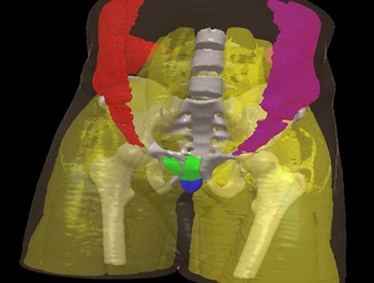
3D-DOCTOR Software is used to extract information from image files to create 3D model. It was developed using object-oriented technology and provides efficient tools to process and analyze 3D images, object boundaries, 3D models and other associated data items in an easy-to-use environment. It does 3D image segmentation, 3D surface modeling, rendering, volume rendering, 3D image processing, disconsolation, registration, automatic alignment, measurements, and many other functions.
3D-DOCTOR supports both grayscale and color images stored in DICOM, TIFF, Interfile, GIF, JPEG, PNG, BMP, PGM, RAW or other image file formats. 3D-DOCTOR creates 3D surface models and volume rendering from 2D cross-section images in real time on your PC. Leading hospitals, medical schools and research organizations around the world are currently using 3D-DOCTOR
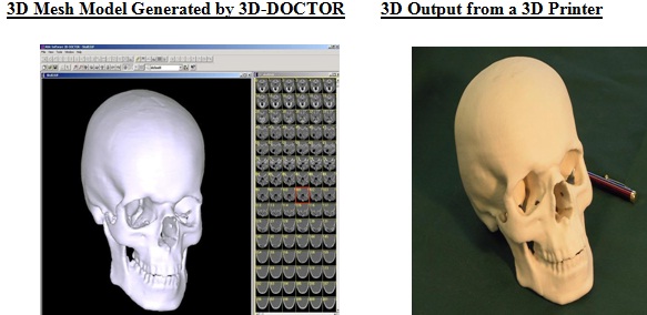
3D-DOCTOR is an advanced, 3D imaging software developed by Able Software Corp.It is an advanced 3D modeling, image processing and measurement software for MRI, CT, PET, microscopy, scientific, and industrial imaging applications. 3D-Doctor supports both grayscale and color images stored in DICOM, TIFF, Interfile, GIF, JPEG, PNG, BMP, PGM, RAW or other image file formats. 3D-DOCTOR creates 3D surface models and volume rendering from 2D cross-section images in real time on your PC. You can export the polygonal mesh models to STL, DXF, IGES, 3DS, OBJ, VRML, XYZ and other formats for surgical planning, simulation, quantitative analysis and rapid prototyping applications. You can calculate 3D volume and make other 3D measurements for quantitative analysis. 3D-DOCTOR's vector-based tools support easy image data handling, measurement, and analysis.3D CT/MRI images can be re-sliced easily along an arbitrary axis.
Multi-modality images can be registered to create image fusions. Misaligned slices can be automatically or semi-automatically aligned using 3D-DOCTOR's image alignment functions. Other image processing functions include template-based film cropping, image reslicing to correct slices of uneven thickness, volume resizing, and image rotation.The 3DBasic scripting tool makes it easy to create Basic-like sophisticated 3D imaging programs.This software does 3D image segmentation, 3D surface modeling, rendering, volume rendering, 3D image processing, deconvolution, registration, automatic alignment, measurements, and many other functions.
3D-DOCTOR supports a variety of image formats in both 2D and 3D. These formats include DICOM, TIFF, JPEG, BMP, Interfile, GIF, PNG and RAW. Other non-standard image formats are also supported, but only with known dimensions (number of columns, rows and planes), bit depth per pixel, little endian or big endian, and the size of file header. 3D-DOCTOR is currently being used by leading hospitals, medical schools and research organizations around the world.
3D- images such as CT, MRI and microscopy images. The following lists some of the main differences between 3D-DOCTOR and other packages: DOCTOR uses its unique vector-based technologies to create better 3D models from volumetric
➢ Unique vector-based technologies for better 3D model creation and easy editing.
➢ Surface model uses smaller number of triangles while maintaining all details for high quality rapid prototyping applications.
➢ Smart memory management with no limit for the number of slices to be used. It has been used to process images with over 2000 slices on a PC with only 256MB RAM.
➢ Single command volume calculation and quantitative analysis report
➢ Handles DICOM and other image formats, such as TIFF, JPEG, PNG, GIF, BMP, Interfile and RAW (vendor proprietary formats).
➢ Works with both grayscale and color images (color classification and separation)
➢ Supports CT, MRI, PET, microscopy, industrial CT, scanned film images, boundary slices, slice data and XYZ points.
➢ High End 3D Image Processing Functions: image registration for multi-modality application, image fusion, image resizing, image reslicing, etc.
➢ Write your own programs with 3DBasic script to automated frequently used steps.
➢ 3D Output Formats: STL (ASCII and Binary), VRML, DXF, 3D Studio, IGES, Wavefront OBJ and more.
➢ Software Reliability: No known bugs in our products because we fix them right away once they are reported.
➢ Reasonably priced.
D-DOCTOR's, 3D surface rendering commands create 3D surface models from object boundary lines or contours. The 3D surface model consists of triangle faces. Multiple objects can be combined together using 3D surface rendering.There are 2 surface rendering commands in 3D-DOCTOR: Simple Surface Rendering and Complex Surface Rendering. They both create 3D surface model but use different algorithms and are suitable for different objects. The simple surface rendering uses a proprietary algorithm to create smooth and simpler surface models.
This method is fast and the models are better suited for rapid prototyping and volume calculation applications. The complex surface rendering uses a triangulation algorithm. This method is slow but robust, and is better for rendering objects with complicated branches and topologies. With 3D-DOCTOR, you can select the proper rendering method for an object and mix multiple objects created using different rendering methods for 3D display.
The following steps explain the process of creating a 3D surface model from images.
Step 1. Open the 3D image using the File/Open Image command.
Step 2. Segment the image using one of the segmentation commands to generate boundaries for an object.
Step 3. Edit the boundary lines using the Edit/Boundary Editor, if necessary. Use the File/Boundary/Export Boundary command to save the boundary data to a file. If you need to render only part of an object, you can use the 3D Rendering/Split Object command to split the object along an arbitrary axis.
Step 4. Now you can create a 3D surface rendering using the 3D Rendering/Surface Rendering commands. You can also create a volume rendering using the 3D Rendering/Volume Rendering command.
3D-DOCTOR can make a variety of image measurements, including distance, area, surface area, volume, profile, and image region histogram. 3D-DOCTOR lets you measure angles using the Angle Measurement tool. 3D volumes of 3D surface models can be calculated easily. When the surface model window is displayed, use the Process/Calculate Volumes command.
For image measurement, 3D-DOCTOR allows you to measure distance, thickness, area of a region, surface area, volume, image density profile and image histogram of a region in any shape. With 3D-DOCTOR, you not only have a number of different ways to visualize your 3D image in 2D, 3D, montage, surface and volume, but also the tools necessary to do accurate quantitative analyses for your applications.
3D-DOCTORÆs restoration functions are the solution to de-blur and restore the 3D image to its original quality with either fast nearest neighbor or maximum entropy deconvolution. It is a complex mathematical problem, but 3D-DOCTOR makes it easy to solve.
3D-DOCTORÆs image registration function, you can register or geometrically correct a 3D image by giving 4 or more control points, easily combine two registered images using one of 8 available methods to create a fusion image.
The volume of a 3D surface model can be calculated easily using the Process/Calculate Volume command within the surface model window. This command computes both volume and surface area. To adjust the scale and unit for volume calculation, the scaling parameters should be entered using the Edit/Calibration command before rendering is done.If you have your 3D model saved in a format supported by 3D-DOCTOR, such as DXF, STL, raw triangle, etc., you can use File/Open Model to read the 3D model into 3D-DOCTOR and then calculate the volume
If you need to do a 3D volume rendering, you can use the "3D Rendering/Volume Rendering/Smooth Rendering" command now. If you want to render different tissue range, go back to the image display, adjust the contrast and then do a volume rendering again.
Step 2. Define objects and create boundary lines for each object. Use the Interactive Segment command to trace object boundaries interactively or the Auto Segment for fully automatic object boundary detection.
Once the interactive segmentation starts, the image plane display is refreshed to apply color to pixels that fall within the threshold range specified by the Min and Max values. Use the slider bar to adjust the Min and Max values. The display of the image slice is updated in real-time according to the current threshold selection. When pixels that belong to the intended object are displayed in color, you can click the “Segment Plane” button to extract the boundaries for the current image plane. Use the “Next Plane” or “Prev Plane” button to go through other planes to segment them individually. If the threshold values are applicable to all slices, you can click on the “Segment All” button to extract boundaries for all image slices. Click “Finish” to leave the interactive segmentation function.
www.seminarsonly.com
| Are you interested in this topic.Then mail to us immediately to get the full report.
email :- contactv2@gmail.com |
