


Published on Apr 02, 2024
Aim is to investigate the relation between:
i) output and input voltage
ii) number of turns in the secondary coil and primary coil of a self designed transformer A transformer is an electrical device which is used for changing the A.C. voltages.
A transformer is most widely used device in both low and high current circuit. As such transformers are built in an amazing strength of sizes. In electronic, measurement and control circuits, transformer size may be so small that it weight only a few tens of grams where as in high voltage power circuits, it may weight hundred of tones.
In a transformer, the electrical energy transfer from one circuit to another circuit takes place without the use of moving parts.
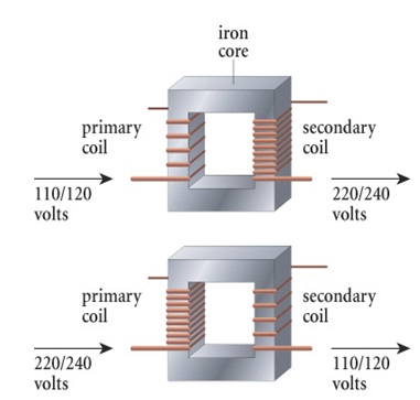
A transformer which increases the voltages is called a step-up transformer . A transformer which decreases the A.C. voltages is called a step-down transformer .
Transformer is, therefore, an essential piece of apparatus both for high and low current circuits. Principle
A Transformer based on the Principle of mutual induction according to this principle, the amount of magnetic flux linked with a coil changing, an e.m.f is induced in the neighbouring coil that is if a varying current is set-up in a circuit induced e.m.f. is produced in the neighboring circuit. The varying current in a circuit produce varying magnetic flux which induces e.m.f. in the neighboring circuit.
The transformer consists of two coils. They are insulated with each other by insulated material and wound on acommon core. For operation at low frequency, we may have asoft iron. The soft iron core is insulating by joining thin ironstrips coated with varnish to insulate them to reduce energy losses by eddy currents.The input circuit is called primary. And theoutput circuit is called secondary.
1. Take a soft iron rod of cm and cm diameter. Wrap thick paper on it.
2. Wind a coil P of enameled copper wire 200 turns.
3. Wind another coil S of thick enameled copper wire with 400 turns.
4. Both coils are wound over same length of the rod, so that almost the entire flux produced by current in one is linked to the other.
5. Connect the coil S with an AC voltmeter. Connect an identical voltmeter across P also.
6. Switch on the current in P and note voltage across the two coils
7. Find the ratio Vp to Vs
1. We will find that ratio of Vp and Vs across the two coils is equal to the ratio of number of turns in the coil P to that in the coil S.i.e.,
Vp/Vs = Np/Ns ---------------(1)
2. The coil P (to which AC voltage is applied) is
Called the primary and coil S (in which AC is induced) is called the secondary.
3.Since coil S is placed very close to the coil P,the power in the primary is transferred into the secondary through mutual induction.
4. It is clear from equation 1, that by appropriate choice of the turn ratio i.e., Np/Ns, we can obtain a higher voltage or lower voltage in S compared to that in P.
Following are the major sources of energy loss in a transformer:
1. Copper loss: is the energy loss in the form of heat in the copper coils of a transformer. This is due to joule heating of conducting wires.
2. Iron loss: is the energy loss in the form of heat in the iron core of the transformer. This is due to formation of eddy currents in iron core. It is minimized by taking laminated cores.
3. Leakage of magnetic flux: occurs inspite of best insulations. Therefore, rate of change of magnetic flux linked with each turn of S1S2 is less than the rate of change of magnetic flux linked with each turn of P1P2.
4. Hysteretic loss: is the loss of energy due to repeated magnetization and demagnetization of the iron core when A.C. is fed to it.
5. Magneto striation: humming noise of a transformer
