


Published on Apr 02, 2024
Electronic eye has much use in this electronic age. Also known as Magic eye. When electric power was first used to light up streets at night, someone in each street became in charge of turning on the light at nights and turn it back off in the mornings.
Today electric eyes automatically turn on the lights when it becomes dark. It can be used as an automatic guest indicator at the door, if fitted at the bottom of the door entrance. Once it is installed at the door there is no need to install a call bell.
An electric eye is a photodetector used for detecting obstruction of a light beam. The device does not provide an image; only presence of light is detectable
1) IC 4049
2) LDR
3) Resistance 220 K ohm
4) Buzzer
5) LED
6) 9V Battery with Snap and
7) a Switch.
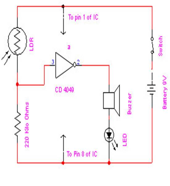

1) IC 4049: This electronic eye circuit uses NOT gate from CMOS I.C CD 4049. CD 4049 contains 6 independent NOT gate in one package; we have used here (a) one only. Advantage of using Logic gate is that data can be easily send to other digital interface device ie one can easily fed data to computer using parallel port or for further processing .
2) LDR: To detect the present of an object we have used LDR and a source of light. LDR is a special type of resistance whose value depends on the brightness of the light which is falling on it. It has resistance of about 1 mega ohm when in total darkness, but a resistance of only about 5k ohms when brightness illuminated. It responds to a large part of light spectrum.
3) BUZZER: Sound is produced through buzzer.
4) 9v BATTERY: The output is powered by 9v battery.
5) SWITCH: It is used to allow or disallow current to pass through the circuit.
6) LED: It is Light Emitting Diode which emits light when forward biased.
When NOT gate output goes high (1) the input pin 3 is at lower and at 1/3rd level of the supply voltage. Conversely the output goes low (0) when it is above 1/3rd level. So small change in the voltage of pin-2 is enough to change the level of output (pin-3) from 1 to 0 and 0 to 1.
The output has only two states high and low and can not remain in any intermediate stage. It is powered by a 9V battery for portable use. The circuit is economic in power consumption. Pin 1 is connected to the positive supply and pin 8 is grounded. LDR used in the circuit is a special type of resistance whose value depends on the brightness of the light which is falling on it.
It has resistance of about 1 mega ohm when in total darkness, but a resistance of only about 5k ohms when brightness illuminated. It responds to a large part of light spectrum. We have made a potential divider circuit with LDR and 220 KΩ resistance connected in series. We know that voltage is directly proportional to conductance so more voltage we will get from this divider when LDR is getting light and low voltage in darkness.
This divided voltage is given to input of NOT gate. As soon as LDR gets dark the voltage of input not gate drops 1/3rd of the supply voltage and pin 2 gets high and LED or buzzer which is connected to the output gets activated.
Hence, when the light beam is made to fall on the LDR and is interrupted, the resistance of LDR increases and IC – 4049 will produce a loud sound in the speaker.
