

Published on Nov 30, 2023
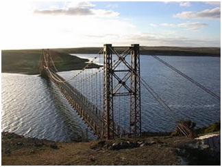
A Stress Ribbon Bridge is a tension structure, similar in many ways to a simple suspension bridge. The stress ribbon design is rare. Few people including bridge engineers are familiar with this form and fewer than 50 have been built worldwide.
The suspension cables are embedded in the deck which follows a catenary arc between supports. Unlike the simple span the ribbon is stressed in compression which adds to the stiffness of the structure. Such bridges are typically made from concrete reinforced by steel tensioning cables. They are used mainly for pedestrian and cycling traffic. Stress ribbon bridges are very economical, aesthetic and almost maintenance free structure. They require minimal quantity of materials. At present studies, on combining stress ribbon bridges with cables or arches, to build most economical stress ribbon bridges.
A typical stress ribbon bridge deck consists of precast concrete planks with bearing tendons to support them during construction and separate prestressing tendons which are tensioned to create the final designed geometric form. The joints between the planks are most often sealed with in-situ concrete before stressing the deck. The prestressing tendons transfer horizontal forces in to the abutments and then to the ground most often using ground anchors. The tendons are encased in ducts which are generally grouted after tensioning in order to lock in the stress and protect them from corrosion. Since the bending in the deck is low, the depth can be minimized and results in reduction in dead load and horizontal forces in abutments.
The abutments are designed to transfer the horizontal forces from the deck cables into the ground via ground anchors. Pedestrians, wind and temperature loads can cause large changes in the bending moments in the deck close to the abutments and accordingly crack widths and fatigue in reinforcement must be considered. The ground anchors are normally tensioned in 2 stages, the first step is tensioned before the deck is erected and the rest, after the deck is complete. If stressed in one stage only, there will be a large out of balance force to be resisted by the abutments in the temporary case. The soil pressure, overturning and sliding has to be checked for construction as well as permanent condition.
The ideal ground condition for resisting large horizontal forces from the ribbon is a rock base. This occurs rarely but suitable foundations can be devised even if competent soils are only found at some depth below the abutments. In some cases where soil conditions do not permit the use of anchors, piles can also be used. Horizontal deformations can be significant and are considered in the design. It is also possible to use a combination of anchors and drilled shafts. Battered micropiling is another alternative which can resist the load from the ribbon because of its compression and tension capacity.
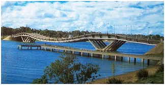
A stress ribbon bridge is a tension structure similar in many ways to a simple suspension bridge. The suspension cables are embedded in the deck which follows a catenary arc between the supports. As opposed to suspension bridges, where the cables carry the load, in stress ribbon, by tensioning the cables and the deck between abutments, the deck shares axial tension forces. Unlike the simple span the ribbon is stressed in compression, which adds to the stiffness of the structure. A simple suspension span tends to sway and bounce. The supports in turn support upward thrusting arcs that allow the grade to be changed between spans, where multiple spans are used.
Such bridges are typically made from concrete reinforced by steel tensioning cables. Where such bridges carry vehicle traffic a certain degree of stiffness is required to prevent excessive flexure of the structure, obtained by stressing the concrete in compression. Anchorage forces are unusually large since the structure is tightly tensioned.
The construction of the bridge is relatively straight forward. The abutments and piers are built first. Next the bearing cables were stretched from abutment to abutment and draped over steel saddles that rested atop the piers. The bearing tendons generally support the structure during construction, and only rarely is additional false work used. Once the bearing cables were tensioned to the specified design force, precast panels were suspended via support rods located at the four corners of each panel. At this point the bridge sagged into its catenary shape.
The next step was to place post tensioning ducts in the bridge. The ducts were placed directly above the bearing cables and support rods, which are all located in two longitudinal troughs that run the length of the bridge. After the ducts were in place, the cast-in place concrete was placed in the longitudinal troughs in small transverse closure joints. Concrete is poured in the joints between the planks and allowed to harden before the final tensioning is carried out. Retarding admixtures may be used in the concrete mix to allow all the concrete to be placed before hardening occurs. Once the final tension has been jacked into the tendons and the deflected shape is verified, the ducts containing the tendons are grouted.
After allowing the cast in place concrete to cure and achieve its full strength, the bridge was post tensioned. The post tensioning lifts each span, closes the gap between the panels, puts the entire bridge in to compression and transforms the bridge in to continuous ribbon of prestressed concrete.
• Stress ribbon pedestrian bridges are very economical, aesthetical and almost maintenance free structures.
• They require minimal quantity of materials.
• They are erected independently from existing terrain and therefore they have a minimum impact upon the environment during construction.
• They are quick and convenient to construct if given appropriate conditions, without false work.
• A stress ribbon bridge allows for long spans with a minimum number of piers and the piers can be shorter than those required for cable stayed or suspension bridges.
• Eco duct: A tunnel which was built as part of a large network of motorways outside Brno. The theory is the same as a self-anchored arch but the geometry is much more complex. It is 50m wide and spans 70m a finite element programme was used in its design.
• Stuttgart trade fair hall roof: The suspended asymmetric roof comprises a regular repetition of stressed trusses with individual I-beam ribbons of steel between them. The trusses function as strut and tie A-frames based on concrete strip foundations and are tied back to the ground with anchors. The stresses in the ribbons and weight of its ‘green roof’ were used to resist wind uplift.
| Are you interested in this topic.Then mail to us immediately to get the full report.
email :- contactv2@gmail.com |
