


Published on Nov 30, 2023
The invention of transistor enabled the first use of radiometry capsules, which used simple circuits for the internal study of the gastro-intestinal (GI) [1] tract. They couldn't be used as they could transmit only from a single channel and also due to the size of the components. They also suffered from poor reliability, low sensitivity and short lifetimes of the devices.
This led to the application of single-channel telemetry capsules for the detection of disease and abnormalities in the GI tract where restricted area prevented the use of traditional endoscopy.
They were later modified as they had the disadvantage of using laboratory type sensors such as the glass pH electrodes, resistance thermometers, etc. They were also of very large size. The later modification is similar to the above instrument but is smaller in size due to the application of existing semiconductor fabrication technologies. These technologies led to the formation of "MICROELECTRONIC PILL".
Microelectronic pill is basically a multichannel sensor used for remote biomedical measurements using micro technology. This is used for the real-time measurement parameters such as temperature, pH, conductivity and dissolved oxygen. The sensors are fabricated using electron beam and photolithographic pattern integration and were controlled by an application specific integrated circuit (ASIC).
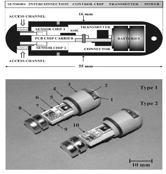
There are basically 4 sensors mounted on two chips- Chip 1 & chip 2. On chip 1(shown in fig 2 a), c), e)), temperature sensor silicon diode (4), pH ISFET sensor (1) and dual electrode conductivity sensor (3) are fabricated. Chip 2 comprises of three electrode electrochemical cell oxygen sensor (2) and optional NiCr resistance thermometer.
An array consisting of both temperature sensor & pH sensor platforms were cut from the wafer & attached onto 100-µm- thick glass cover slip cured on a hot plate. The plate acts as a temporary carrier to assist handling of the device during level 1 of lithography when the electric connections tracks, electrodes bonding pads are defined. Bonding pads provide electrical contact to the external electronic circuit.
Lithography [2] was the first fundamentally new printing technology since the invention of relief printing in the fifteenth century. It is a mechanical Plano graphic process in which the printing and non-printing areas of the plate are all at the same level, as opposed to intaglio and relief processes in which the design is cut into the printing block. Lithography is based on the chemical repellence of oil and water. Designs are drawn or painted with greasy ink or crayons on specially prepared limestone. The stone is moistened with water, which the stone accepts in areas not covered by the crayon. Oily ink, applied with a roller, adheres only to the drawing and is repelled by the wet parts of the stone. Pressing paper against the inked drawing then makes the print.
Lithography was invented by Alois Senefelder in Germany in 1798 and, within twenty years, appeared in England and the United States. Almost immediately, attempts were made to print pictures in color. Multiple stones were used; one for each color, and the print went through the press as many times as there were stones. The problem for the printers was keeping the image in register, making sure that the print would be lined up exactly each time it went through the press so that each color would be in the correct position and the overlaying colors would merge correctly.
Early colored lithographs used one or two colors to tint the entire plate and create a watercolor-like tone to the image. This atmospheric effect was primarily used for landscape or topographical illustrations. For more detailed coloration, artists continued to rely on hand coloring over the lithograph. Once tinted lithographs were well established, it was only a small step to extend the range of color by the use of multiple tint blocks printed in succession. Generally, these early chromolithographs were simple prints with flat areas of color, printed side-by-side.
Increasingly ornate designs and dozens of bright, often gaudy, colors characterized chromolithography in the second half of the nineteenth century. Overprinting and the use of silver and gold inks widened the range of color and design. Still a relatively expensive process, chromolithography was used for large-scale folio works and illuminated gift books that often attempted to reproduce the handwork of manuscripts of the Middle Ages. The steam-driven printing press and the wider availability of inexpensive paper stock lowered production costs and made chromolithography more affordable. By the 1880s, the process was widely used for magazines and advertising. At the same time, however, photographic processes were being developed that would replace lithography by the beginning of the twentieth century.
The microelectronic pill consists of a machined biocompatible (non-cytotoxic), chemically resistant polyether-terketone (PEEK) capsule and a PCB chip carrier acting as a common platform for attachment of sensors, ASIC, transmitter & batteries (fig 1.). The fabricated sensors were each attached by wire bonding to a custom made chip carrier made from a 10-pin, 0.5-pitch polymide ribbon connector.
The connector in turn was connected to an industrial STD. flat cable plug (FCP) socket attached to the PCB carrier chip of the microelectronic pill, to facilitate the rapid replacement off the sensors when required. The PCB chip carrier was made from 2 STD. 1.6 mm-thick fiber glass boards attached back to back epoxy resin which maximized the distance between the 2 sensor chips. The sensor chips are connected to both sides of the PCB by separate FCP sockets, with sensor chip 1 facing the top face, with the sensor chip 2 facing down.
Thus, the oxygen sensor on chip 2 had to be connected to the top face by 3 200 nm copper leads soldered onto the board. The transmitter was integrated in the PCB which also incorporated the power supply rails, the connection points to the sensors, as well as the transmitter & the ASIC & the supporting slots for the capsule in which the carrier is located.
The ASIC was attached with double-sided Cu conducting tape prior to wire bonding to the power supply rails, the sensor inputs & the transmitter (a process which entailed the connection of 64 bonding pads). The unit was powered by 2 STD. 1.55V SR44 Silver oxide (Ag2O) cells with a capacity of 175mAh. The batteries were connected & attached to a custom made 3-pin, 1.27 mm pitch plug by electrical epoxy. The connection on the matching socket on the PCB carrier provided a three point power supply to the circuit comprising a negative supply rail (1.55V).
The capsule was machined as two separate screw-fitting compartments. The PCB chip carrier was attached to the front section of the capsule (fig 1.). The sensor chips were exposed to the ambient environment through access ports & were sealed by 2 stainless steel clamps incorporating a 0.8 µm thick sheet of Viton fluoroelastometer seal. A 3 mm dia access channel in center of each of the steel clamps (incl. the seal), exposed in sensing regions of the chips. The rear section of the capsule is attached to the front section by a 13 mm screw connection incorporating a Viton rubber O-ring. The seals rendered the capsule water proof, as well as making it easy to maintain (e.g. during sensor & battery replacement)
The complete prototype was 16*55 mm & weighs 13.5 g including the batteries.
The generic nature of microelectronic pill makes it adaptable for use in corrosive environments related to environmental & industrial applications, such as the evaluation of water quality, pollution detection, fermentation process control & inspection of the pipelines. The integration of radiation sensors & the application of indirect imaging technologies such as ultrasound & impedance tomography, will improve the detection of tissue abnormalities & radiation treatment associated with cancer & chronic inflammation.
Further developments focus on the photo pattern able gel electrolyte and oxygen and cat ion selective membranes. Also in the future, these measurements will be used to perform physiological analysis of the GI tract. For e.g., Temperature sensors can be used to measure the body core temperature, also locate any changes corresponding to ulcers or tissue inflammation; pH sensors may be used for determination of presence of pathological conditions associated with abnormal ph levels etc
In the future, one objective would be to produce a device, analogous to a micro total analysis system (µTAS) or lab on a chip sensor which is not only capable of collecting & processing data, but which can transmit it from a remote location. The overall concept would be to produce an array of sensor devices distributed throughout the body or environment, capable of transmitting high-quality information in real time.
We have therefore described about the multichannel sensor, which has been implemented in remote biomedical using micro technology, the micro electronic pills, which is designed to perform real time measurements in the GI tract providing the best in vitro wireless transmitter, multi channel recordings of analytical parameter
| Are you interested in this topic.Then mail to us immediately to get the full report.
email :- contactv2@gmail.com |
